
Method for continuously measuring melting steel temperature and measuring temperature pipe

a technology of molten steel and temperature measurement, which is applied in the direction of heat measurement, optical radiation measurement, instruments, etc., can solve the problems of inability to describe the structure of the tube in detail and teach, high measurement cost, and difficulty in acceptance by steel making plants, etc., to achieve stable radiation of the blackbody cavity, low cost, and high precision

Inactive Publication Date: 2005-01-25
NORTHEASTERN UNIV +1
View PDF23 Cites 17 Cited by
  • Summary
  • Abstract
  • Description
  • Claims
  • Application Information

AI Technical Summary

Benefits of technology

The object of the invention is to provide a method and a tube for measuring the temperature of molten steel continuously with low cost and high precision.
Based on heat transfer analysis and blackbody cavity theory, according to the invention, the structure of the tube and the length of the tube under the surface of the molten steel are specified so that stable radiation of the blackbody cavity can be obtained. Accordingly, the temperature of the molten steel can be measured continuously with low cost and high precision.

Problems solved by technology

However, the protector's lifetime is limited because of the erosion of steel residue and the thermo-couple is expensive, so the cost of measurement is high, which is difficult to be accepted by steel making plants.
However, many disadvantages exist in this patent.
This patent fails to describe the structure of the tube in detail and teach how deeply the tube should be put into the molten steel.
Consequently, errors will occur in the results of the measurement.
Secondly, graphite used at the end of the tube is of strong volatility under high temperature environment, and the volatile gas can pollute the optical path and significantly affect the accuracy of the measurement.

Method used


Image

  • Method for continuously measuring melting steel temperature and measuring temperature pipe
  • Method for continuously measuring melting steel temperature and measuring temperature pipe
  • Method for continuously measuring melting steel temperature and measuring temperature pipe

Examples


Embodiment Construction

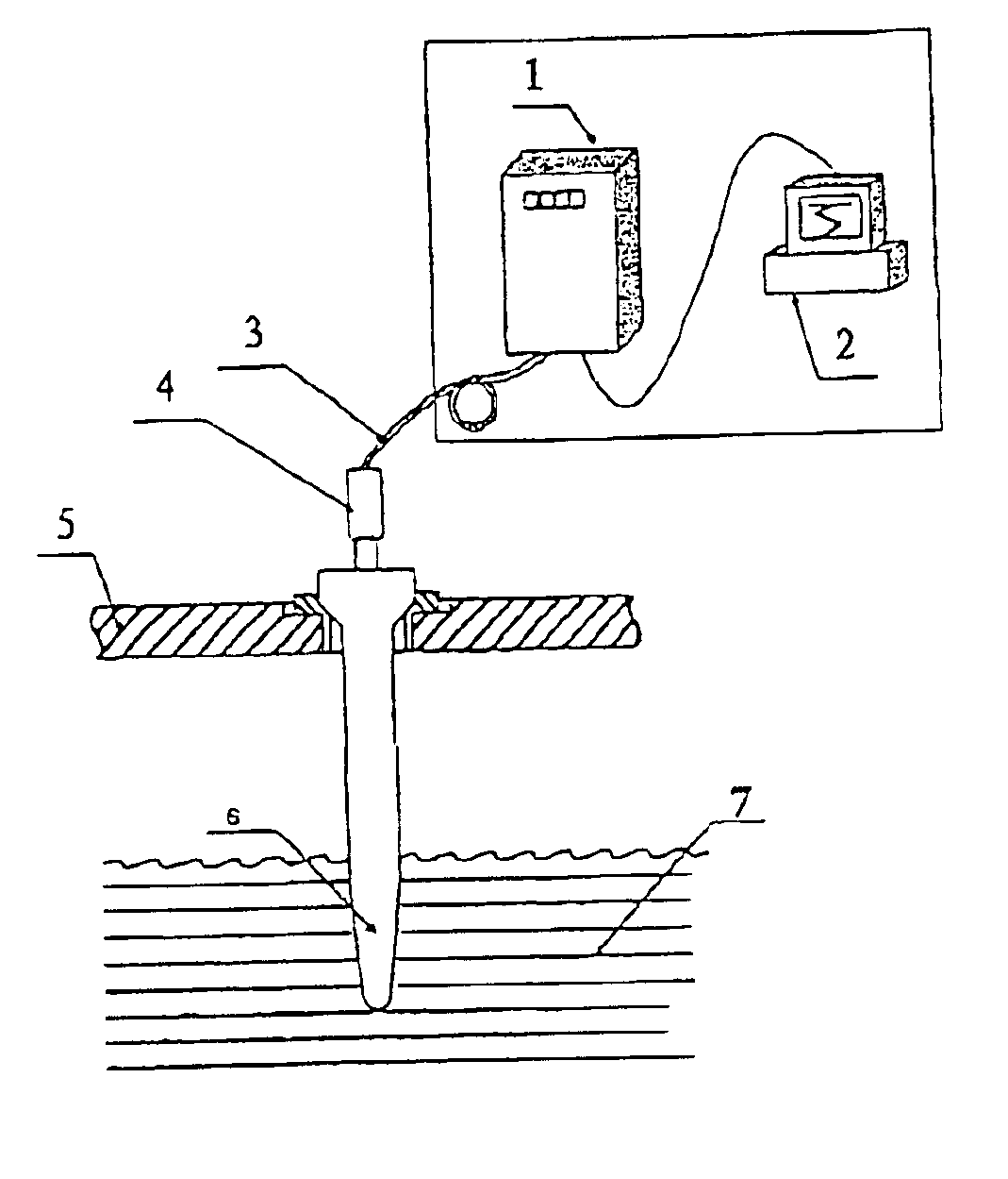
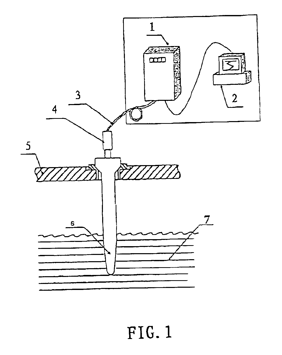
As shown in FIG. 1, the device for measuring the temperature of molten steel continuously according to the method of the invention comprises a tube 6, an infrared detector 4, an optical fibre 3, a signal processor 1 and a computer 2. In operation, the tube 6 is fixed to a holder 5 and put into the molten steel 7. There is provided a cone-shaped connector at the open end of the tube 6, in order to connect with the infrared detector 4, in which a corresponding cone-shaped concave is formed to facilitate replacing the tube.

Considering the tube has to be put into the molten steel, it should be of excellent heat-resistance, molten steel scour-resistance, vibration-resistance, stability and accuracy. Therefore, the tube 6 is made of double bushings, as shown in FIG. 2. Both of the inner bushing 8 and the outer bushing 9 are close at one end and open at another end. The close end of the tube is put into the molten steel 7, and the open end is connected to the infrared detector 4 by a conne...


PUM


Abstract

The invention discloses a method for measuring the temperature of a molten steel continuously, comprises the following steps: providing a tube that is made of double bushings, both of the inner and outer bushings being close at one end and open at another end; putting the close end of the tube into the molten steel in such a way that the ratio of the length of the tube under the surface of the molten steel to the inner diameter of the inner bushing is equal or greater than 15 and the ratio of said length to the outer diameter of the outer bushing is greater than 3; connecting the open end of the tube with an infrared detector; and calculating the temperature of the molten steel through evaluating the radiation emitted by the inner bushing at the end that was put under the molten steel by means of the detector. A tube to implement the method is also disclosed.

Description

TECHNICAL FIELDThe present invention relates to a method for measuring the temperature of molten steel continuously and a tube used for implementing said method.BACKGROUND OF THE INVENTIONIn metallurgy, the temperature of molten steel needs to be measured continuously. The steel making process is essentially the process of controlling the temperature and the ingredients of the molten steel, so measuring the temperature of the molten steel continuously is significant for improving productive efficiency, decreasing energy consumption and improving quality. The conventional technique for the measurement works in an object-contacted way. A platinum-rhodium thermo-couple with a protector is put into the molten steel to sense the temperature. However, the protector's lifetime is limited because of the erosion of steel residue and the thermo-couple is expensive, so the cost of measurement is high, which is difficult to be accepted by steel making plants.U.S. Pat. No. 3,432,522 discloses a ...

Claims


Application Information

Patent Timeline
IPC IPC(8): G01J5/08G01J5/00G01J5/02
CPCG01J5/0887G01J5/0818G01J5/08G01J5/046G01J5/004G01J5/02
Inventor XIE, ZHICHEN, RUJUNMENG, HONGJI
Owner NORTHEASTERN UNIV
Learn More