
Rotating fluid evaporator and condenser

a rotating fluid and condenser technology, applied in the field of distillation systems, can solve the problems of many hours, inefficient production of anything other than small amounts of distilled water, and inability to produce a few gallons of distilled water

Inactive Publication Date: 2005-01-25
ZANAQUA TECH
View PDF34 Cites 24 Cited by
  • Summary
  • Abstract
  • Description
  • Claims
  • Application Information

AI Technical Summary

Problems solved by technology

These boiler-type distillers require substantial amounts of electrical power to produce relatively little distilled water, and are thus highly inefficient for producing anything other than small amounts of distilled water.
They are also extremely slow, often taking many hours to produce just a few gallons of distilled water.
Accordingly, boiling-type distillers have not gained widespread acceptance or use.
The vapor is not, however, able to enter the sealed spaces.
Although it may provide some advantages, the design of the '159 evaporator presents a substantial risk of contamination of the condensate by the liquid being evaporated, and is thus not suitable to generating potable distilled water.
In other words, with the evaporator of the '159 patent, the unsafe water which is being distilled could mix with, and thus contaminate, the distillate.
For example, a leak at any of the sealed spaces would allow liquid from the sealed space to enter the housing and mix with the distillate being collected therein.
Rotary plate evaporators, such as the evaporator disclosed in the '159 patent, can also be relatively expensive to manufacture, in large part, due to the inefficient use of materials.
This often produces a significant amount of “waste” copper (i.e., the remaining portions of the rectangular sheet).
These distillers, however, do not scale well to smaller systems.
For example, the operating costs associated with the centrifugal compressor make them impractical for installations that require only tens of gallons of distilled water a day.

Method used


Image

  • Rotating fluid evaporator and condenser
  • Rotating fluid evaporator and condenser
  • Rotating fluid evaporator and condenser

Examples


Embodiment Construction

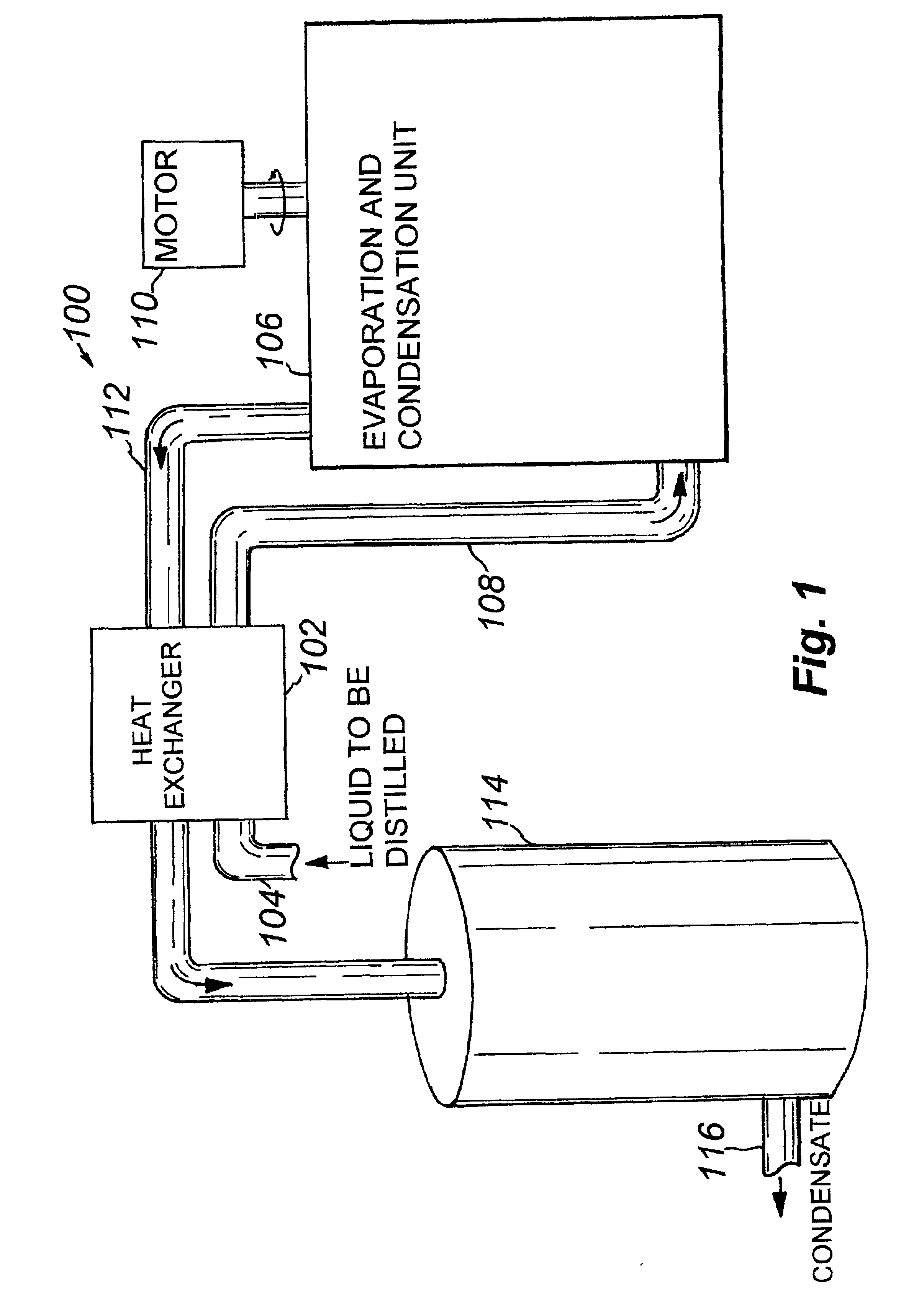
. 1 is a schematic diagram of a vapor compression distillation system 100 in accordance with the present invention. Generally, the system 100 comprises a heat exchanger, such as counter-flow heat exchanger 102, for heating a supply of liquid to be distilled, such as non-potable water, which is received by heat exchanger 102 by first pipe 104. Heated liquid is transferred from the heat exchanger 102 to an evaporation and condensation unit 106 by a feed line 108. Coupled to the evaporation and condensation unit 106 is a motor 110 for supplying rotary power thereto. An output line 112 transfers a condensate, such as distilled water, from the evaporation and condensation unit 106 back through the heat exchanger 102. The condensate is then stored in a holding tank 114. Condensate may be withdrawn from the holding tank 114 by a second pipe 116.

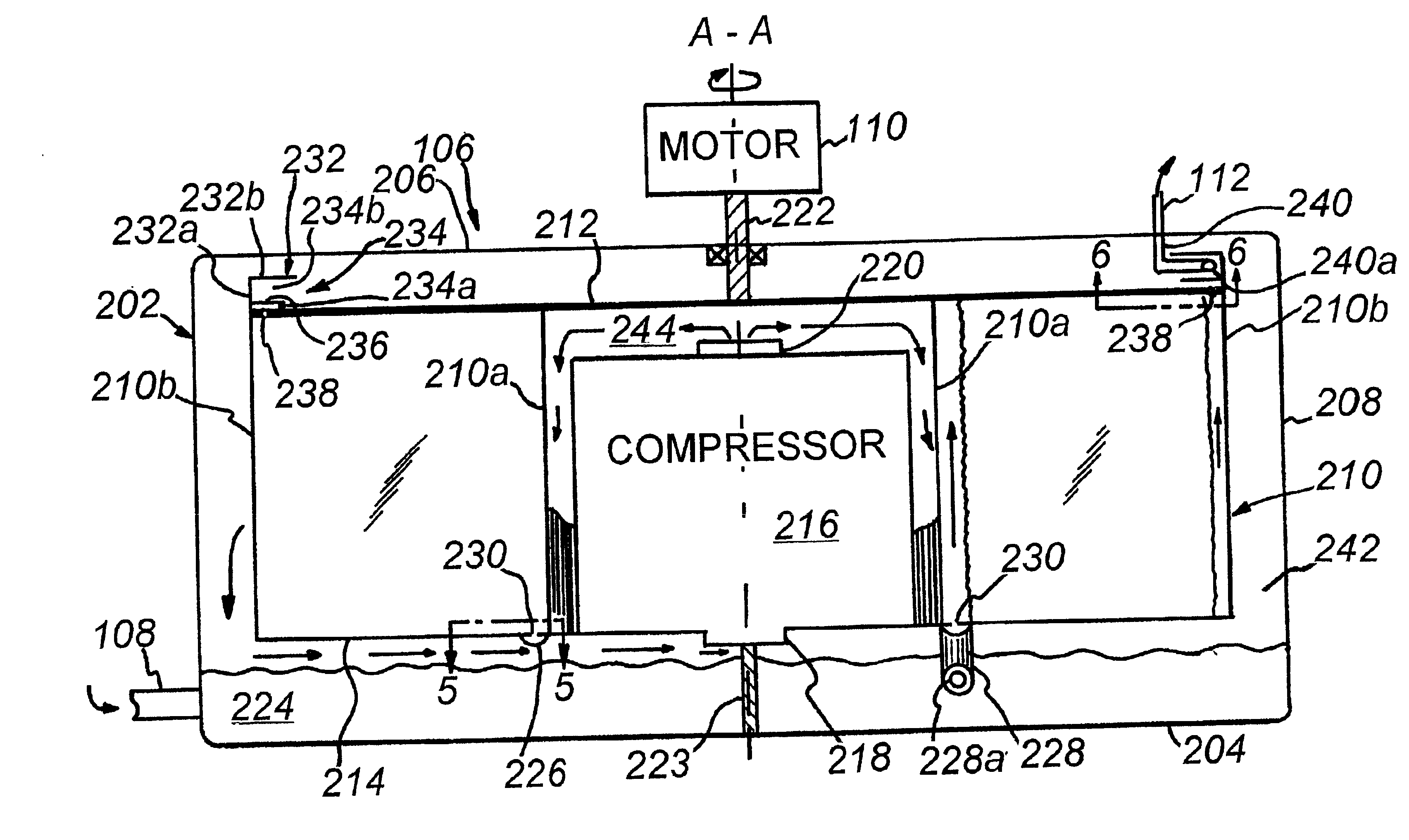
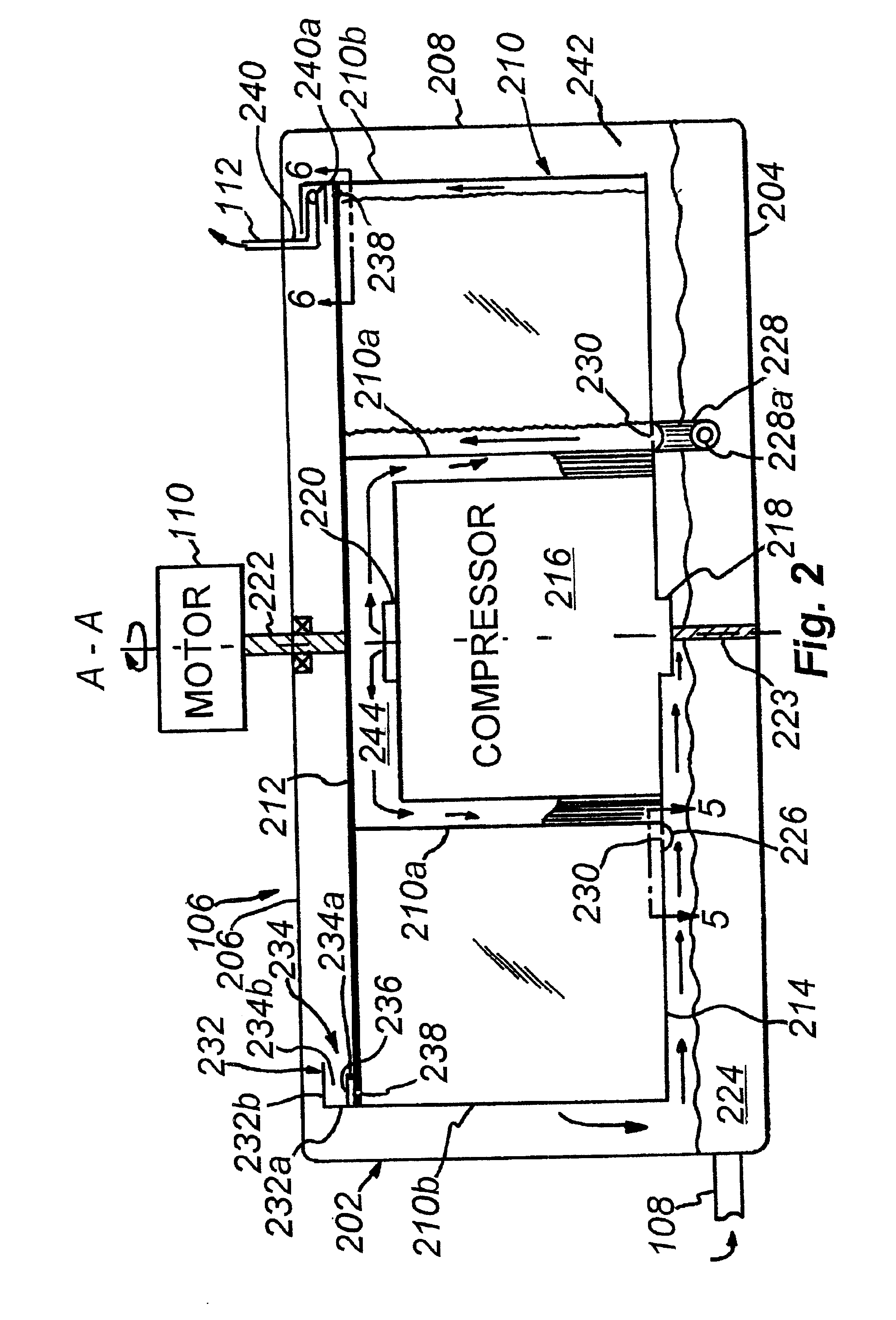
FIG. 2 is a highly schematic, cross-sectional view the evaporation and condensation unit 106 and motor 110 of FIG. 1. The unit 106 includes a housi...


PUM

PropertyMeasurementUnit
diameteraaaaaaaaaa
diameteraaaaaaaaaa
diameteraaaaaaaaaa

Abstract

An evaporator and condenser unit for use in distilling a liquid, such as water, includes a rotary heat exchanger plate having a plurality of accordion-style folds, and having its two ends joined together so as to give the folded plate a generally circular form. The adjacent panels of the folded plate define spaces between their oppositely facing surfaces, and these spaces are alternatingly configured as evaporating and condensing chambers. The evaporating chambers have their inner edges sealed by corresponding folds, while the condensing chambers have their outer edges sealed by corresponding folds. The folded plate is disposed between first and second end plates, and is mounted for rotation about its axis in a housing having a sump containing the liquid to be distilled. Liquid is supplied to the evaporating chambers and compressed vapor is supplied to the condensing chambers. Condensate is removed from the condensing chambers.

Description

BACKGROUND OF THE INVENTION1. Field of the InventionThis invention relates to distillation systems and, more specifically, to an improved, highly efficient, rotary evaporator and condenser for use in a vapor compression distiller.2. Background InformationDistillation is a well-known method for generating potable water from otherwise unsafe water sources (such as sea water or polluted ground water). With distillation, water is heated to boiling, and the resultant vapor (i.e. steam) is collected and condensed, producing distilled water. Many contaminants that are present in the water source are left behind when the water is converted to its vapor phase. Conventional small distillers typically incorporate and electric heating element to boil water in a tank. A condensing coil mounted above the tank collects the vapor and condenses it. The distilled water is then transferred to a holding tank or cell. These boiler-type distillers require substantial amounts of electrical power to produc...

Claims


Application Information

Patent Timeline
Patent Type & Authority Patents(United States)
IPC IPC(8): B01D5/00B01D1/22B01D1/00B01D1/28C02F1/04
CPCB01D1/222B01D1/28C02F1/04B01D5/0069B01D5/0024
Inventor ZEBUHR, WILLIAM H.
Owner ZANAQUA TECH
Learn More