Adiabatic compressed air energy storage system with liquid thermal energy storage

a technology of compressed air and energy storage system, which is applied in the direction of machine/engine, lighting and heating apparatus, and combination engines. it can solve the problems of large high temperature and high pressure, and high temperature and high pressure, and achieve the effect of increasing cost and long development time, and increasing the duty of the tes uni

Inactive Publication Date: 2011-05-05
GENERAL ELECTRIC CO
View PDF13 Cites 167 Cited by
  • Summary
  • Abstract
  • Description
  • Claims
  • Application Information

AI Technical Summary

Problems solved by technology

The use of a single TES unit results in the TES unit being forced to operate at a high temperature and high pressure.
The high temperature, high pressure, and large duty of the TES unit pose engineering challenges with regard to material, thermal expansion, heat losses, size and mechanical stresses.
The need to address these engineering challenges leads to increased cost and long development times and presents a steep market barrier.
Additionally, the use of a single TES unit also results in decreased efficiency of the ACAES system.
An ACAES system implementing two TES units has been proposed by the German Aerospace Center (DLR); however, such an arrangement of two TES units still does not completely address the issues of temperature and pressure.
The presence of such high temperatures of operation remains a substantial barrier for implementing ACAES systems in commercial operation.

Method used


Image

  • Adiabatic compressed air energy storage system with liquid thermal energy storage
  • Adiabatic compressed air energy storage system with liquid thermal energy storage

Examples


Embodiment Construction

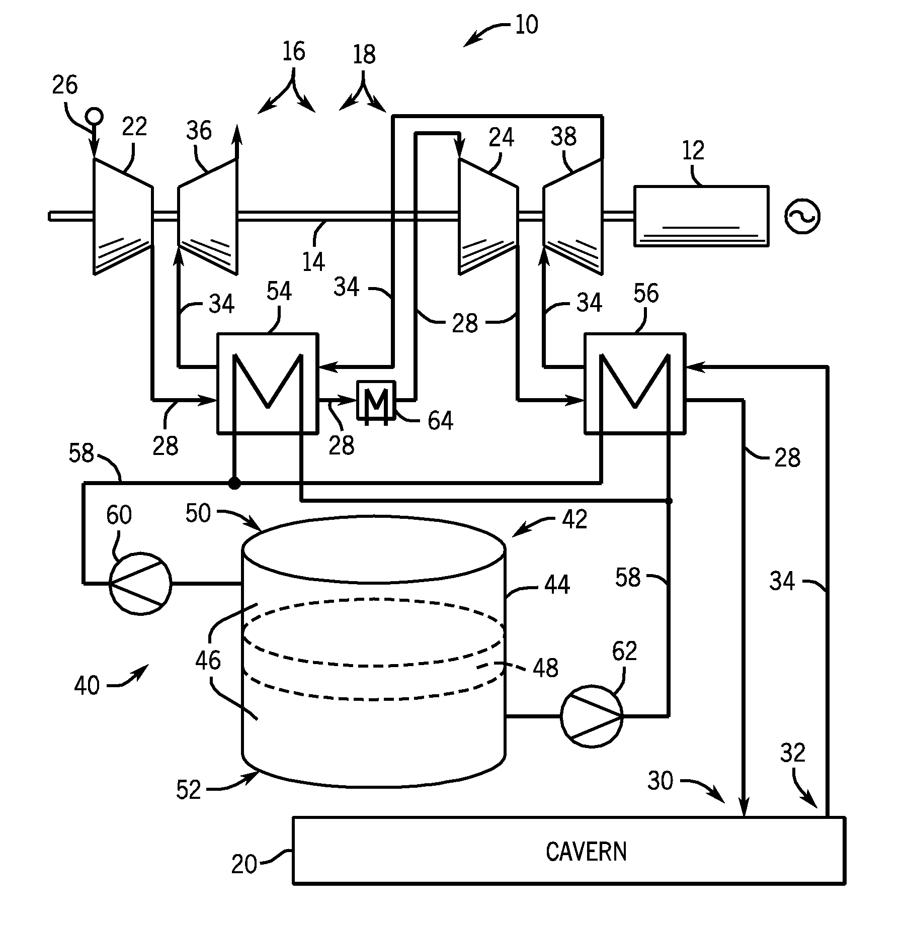
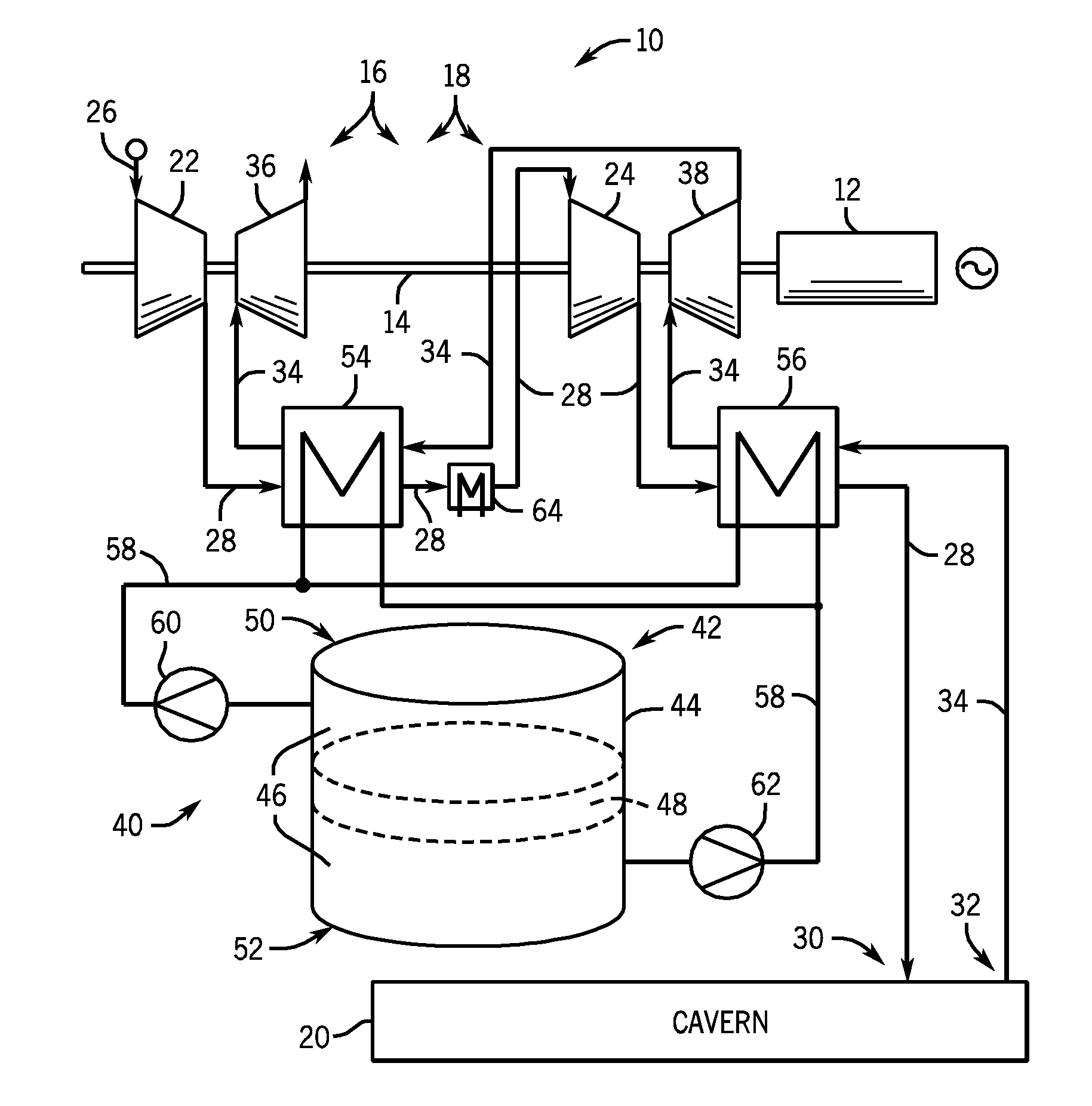
[0016]Embodiments of the invention provide a multi-stage ACAES system with a TES system. The multi-stage ACAES system preferably includes a two-stage compression / expansion system including a low pressure stage and a high pressure stage; however, embodiments of the invention may include more than two stages. The TES system preferably includes a liquid TES system having a heat exchanger for each stage of compression / expansion. The TES system also preferably includes a single tank holding a liquid TES medium that is simultaneously pumped through the heat exchangers during operation. The tank is preferably configured to separate a hot liquid TES medium therein from a cold liquid TES medium therein via a separation system that may include, for example, (1) stratification due to gravity and a system to prevent mixing and convection, (2) separation via a floating piston, or (3) having a thermocline and regenerative thermal storage with solid inventory material.

[0017]Referring now to FIG. 1...


PUM


Abstract

An adiabatic compressed air energy storage (ACAES) system includes a compressor system, an air storage unit, and a turbine system. The ACAES system further includes a thermal energy storage (TES) system that includes a container, a plurality of heat exchangers, a liquid TES medium conduit system fluidly coupling the container to the plurality of heat exchangers, and a liquid TES medium stored within the container. The TES system also includes a plurality of pumps coupled to the liquid TES medium conduit system and configured to transport the liquid TES medium between the plurality of heat exchangers and the container, and a thermal separation system positioned within the container configured to thermally isolate a first portion of the liquid TES medium at a lower temperature from a second portion of the liquid TES medium at a higher temperature.

Description

BACKGROUND OF THE INVENTION[0001]Embodiments of the invention relate generally to compressed air energy storage (CAES) systems and, more particularly, to a multi-stage thermal energy storage (TES) system in an adiabatic CAES system.[0002]Air compression and expansion systems are used in a multitude of industries for a variety of applications. For example, one such application is the use of air compression and expansion systems for storing energy. Compressed air energy storage (CAES) systems typically include a compression train having a plurality of compressors that compress intake air and provide the compressed intake air to a cavern, underground storage, or other compressed air storage component. The compressed air is then later used to drive turbines to produce electrical energy. During operation of the compression stage of a CAES system, the compressed intake air is typically cooled. During operation of the expansion stage, air is discharged from underground storage through heat...

Claims


Application Information

Patent Timeline
Patent Type & Authority Applications(United States)
IPC IPC(8): F02C6/16F02C1/05F02C6/02F01K23/16F01K23/18
CPCF02C1/005F02C6/16F05D2220/60F02C7/10Y02E60/15F02C6/18Y02E60/16
Inventor FREUND, SEBASTIAN W.FINKENRATH, MATTHIASBOTERO, CRISTINABELLONI, CLARISSA S.K.GONZALEZ SALAZAR, MIGUEL ANGELHOFFMANN, STEPHANIE MARIE-NOELLE
Owner GENERAL ELECTRIC CO
Why Eureka
Try Eureka