Oxidant control in co-generation installations

a co-generation and oxidant control technology, applied in the field of co-generation, can solve the problems of high cost of such a heat exchanger, prohibitive implementation of such a scheme, and disadvantage of introducing a large heat exchanger before the gas turbin

Inactive Publication Date: 2001-06-19
LAIR LIQUIDE SA POUR LETUDE & LEXPLOITATION DES PROCEDES GEORGES CLAUDE +1
View PDF21 Cites 172 Cited by
  • Summary
  • Abstract
  • Description
  • Claims
  • Application Information

AI Technical Summary

Problems solved by technology

Efficient power generation represents one of the major challenges of the present generation.
This process has the advantage of using low quality fuel, but has the disadvantage of introducing a large heat exchanger before the gas turbine.
The high cost of such a heat exchanger may be prohibitive for the implementation of such a scheme.
One of the drawbacks of this invention is the pressure loss in the compressed air heat exchanger, leading to efficiency losses.
This scheme, although seemingly efficient in lowering NOx emissions, complicates the installation design.
This cold air lowers the combustion temperature, and for low heating value

Method used


Image

  • Oxidant control in co-generation installations
  • Oxidant control in co-generation installations
  • Oxidant control in co-generation installations

Examples


first embodiment

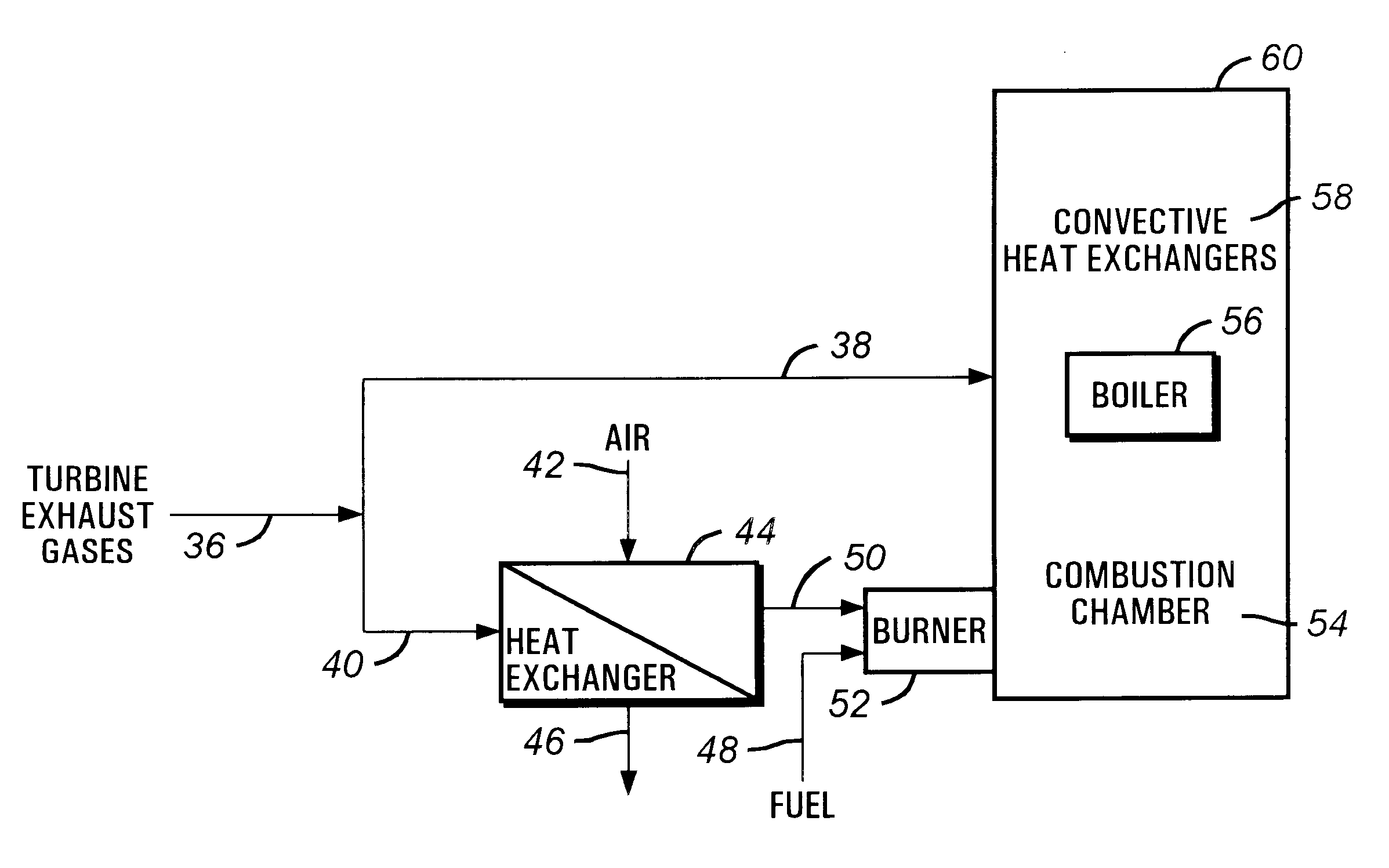
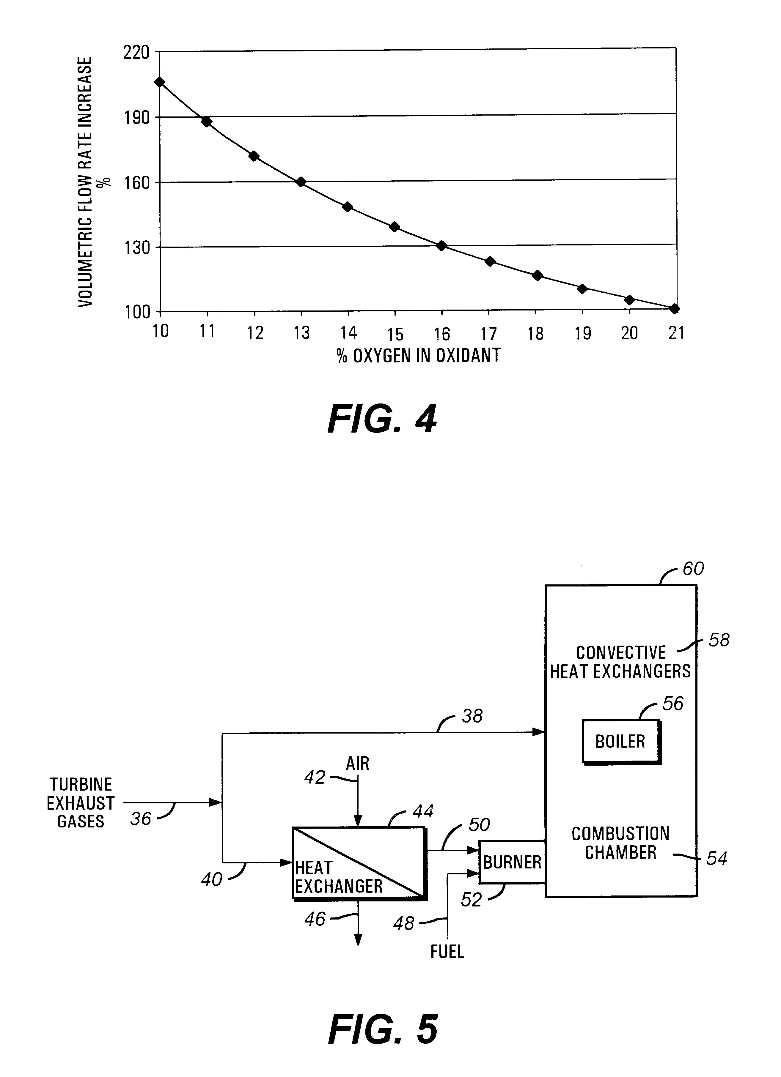
FIG. 5 presents this invention. The exhaust gases 36 exiting the gas turbine are separated into two streams, a first and second stream 38 and 40. One stream 38 is directed to the boiler, as in prior art. One difference from the prior art is that this stream 38 of turbine exhaust gases is directed to the convective part of the boiler (56, 58). This way combustion chamber 54 will operate at higher temperatures, more efficient from a radiative heat transfer standpoint. The second stream of the turbine exhaust gas 40 is sent to a heat exchanger 44 where the turbine exhaust gases 40 heat a stream of ambient air 42. Cooled turbine exhaust gases 46 can be released in the atmosphere, and the preheated air 50 represents the new, improved oxidant. If the original turbine exhaust gases contain 13% oxygen, it can be considered that this process enriches the oxidant about 60%, with a significant impact on boiler combustion.

Ambient air 42 into the heat exchanger can theoretically be heated up to ...

fourth embodiment

It is noted that the fourth embodiment in FIG. 9 envisions preferably the use of oxidants with high concentrations of oxygen, such as provided from a liquid oxygen source, or from an on-site generation unit (with oxygen concentrations of 85% and above), for example membrane, TSA, PSA or VSA, or cryogenic air separation unit. The addition of oxygen is intended to improve the combustion process, particularly in the presence of low calorific value fuels, such as waste fuels. The implementation of oxygen enrichment in the boiler has been extensively investigated in a previous patent application Ser. No. 09 / 329,555, filed Jun. 10, 1999, incorporated by reference herein, and all the advantages / techniques of that patent can be applied in the co-generation boiler units. In this circumstance, the sensor(s) 62 in combustion chamber 54 may monitor, besides the oxygen content, the unburnt fuel, carbon monoxide, flame temperature, and the like. The control scheme is more involved in this case du...


PUM


Abstract

This invention is related to so-called combined cycle co-generation installations, and it addresses present concerns of the industry. Among these, combustion stability, corrosion (due to large water content in the flue gases), large heat transfer areas, and the like. In some embodiments, an additional heat exchanger is added to heat combustion air with a portion of the exhaust gases resulting from an engine, preferably a gas turbine. As a result, the efficiency of the cycle will improve, the oxidant will be enriched by above 50% oxygen, the combustion process will be enhanced, and the dimensions of the boiler may be reduced. It is considered that the combustion air will require between 10% and 80% of the total flue gas volume, more preferably between 20% and 40%. This is the portion of the flue gases sent through the heat exchanger. A control system designed to optimize the flow of the different streams is also presented. Other inventive embodiments forego heat exchanges in lieu of precise control of two flows of exhaust gas, with preferred addition of additional oxidant to the boiler bumers.

Description

1. Field of the InventionThis invention is directed generally to co-generation, and in particular to improvements therein.2. Related ArtEfficient power generation represents one of the major challenges of the present generation. Huge power demands require a major effort from the industry, with great implications on world resources and the environment. Clean, efficient power generation methods are being sought by technical groups worldwide.Co-generation has become one of the preferred choices for small and medium power generation units, due to its increased efficiency and adaptability. The combined gas turbine / steam generation cycle has evident advantages in terms of overall thermodynamic efficiency and also addresses industry power / heat requirements.Extensive work emphasized in patents and publications has been generated on co-generation. Thus, Sakai et al. (U.S. Pat. No. 4,106,286) propose the concept in FIG. 3 of the present application, together with a de-nitration device placed ...

Claims


Application Information

Patent Timeline
IPC IPC(8): F01K23/10F22B1/00F23G5/50F22B1/18
CPCF01K23/105F22B1/1861F23G5/50F23G2206/202F23L2900/07005F23L2900/15043Y02E20/16Y02E20/344Y02E20/34
Inventor MARIN, OVIDIUCHARON, OLIVIERSAMANIEGO, JEAN-MICHELSEGRET, JACQUES
Owner LAIR LIQUIDE SA POUR LETUDE & LEXPLOITATION DES PROCEDES GEORGES CLAUDE
Why Eureka
Try Eureka