Permanent magnet rotor assembly for interior permanent magnet electric motor

Active Publication Date: 2005-01-25
IND TECH RES INST
View PDF7 Cites 80 Cited by
  • Summary
  • Abstract
  • Description
  • Claims
  • Application Information

AI Technical Summary

Benefits of technology

It is therefore an object of the present invention to provide a permanent magnet rotor assembly for a brushless electric motor suitable to drive an ele

Problems solved by technology

So there is no way to install larger motors.
Furthermore, traction motor of electric vehicles requires high rotational speeds and is always with flux weakening control.
When the rotor 1 is under heavy load, the magnetic field increases due to the re

Method used


Image

  • Permanent magnet rotor assembly for interior permanent magnet electric motor
  • Permanent magnet rotor assembly for interior permanent magnet electric motor
  • Permanent magnet rotor assembly for interior permanent magnet electric motor

Examples


Embodiment Construction

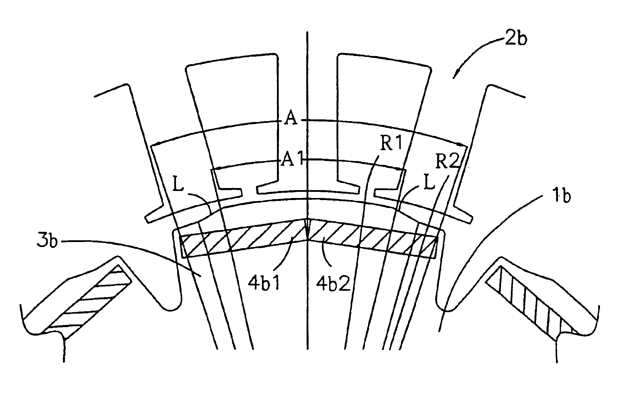
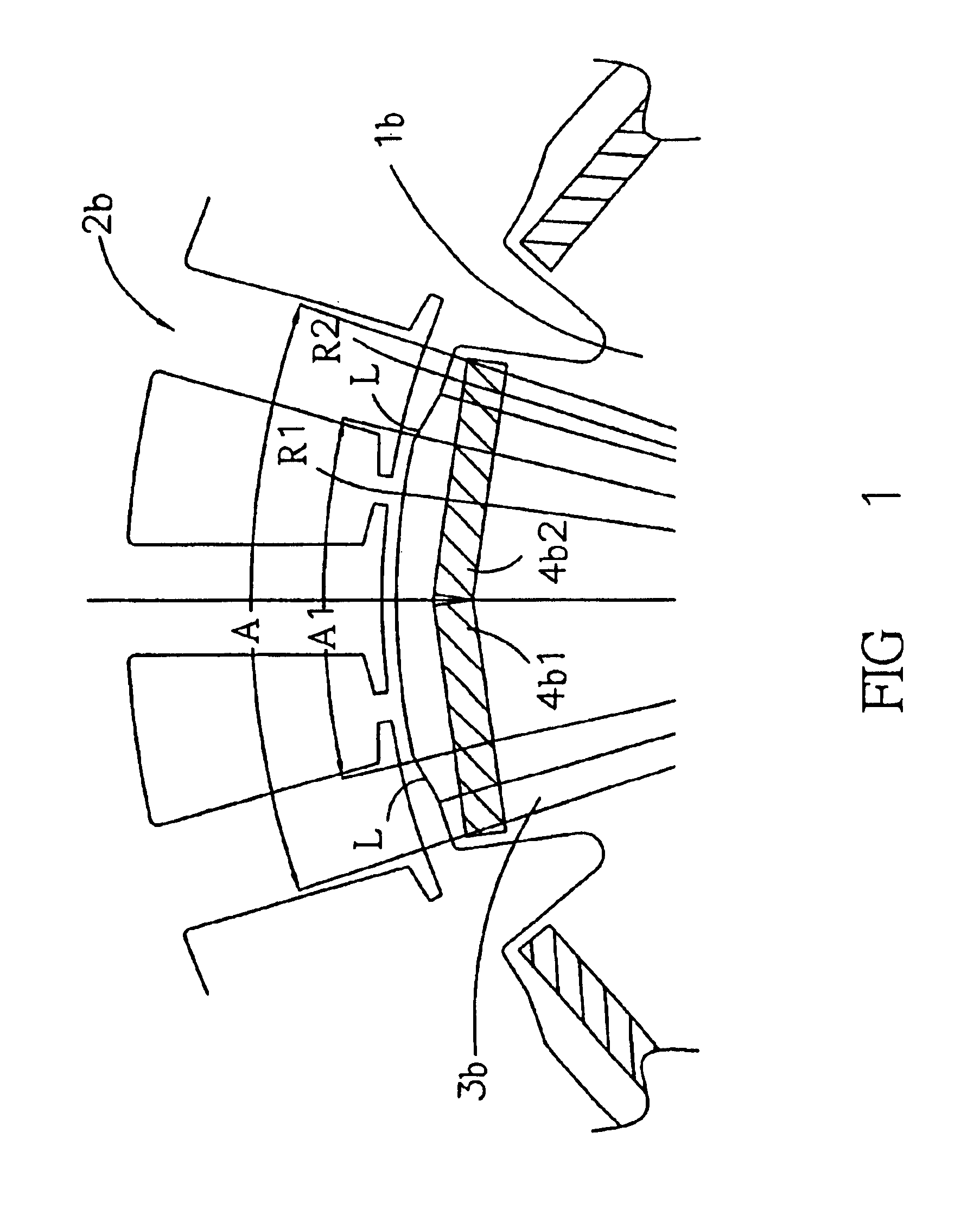
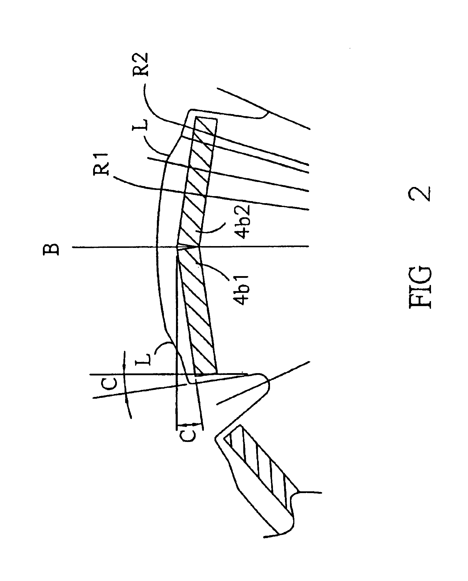
The rotor permanent magnet rotor assembly for a brushless electric motor of the present invention improves on conventional art using a single-plate permanent magnet 4, as shown in FIG. 5, and a single-plate permanent magnet 4a, as shown in FIG. 6, by having a dual-plate permanent magnet composed of outward protruding plates 4b1, 4b2, as shown in FIG. 1. The rotor assembly of the present invention further comprises a rotor 1b, a stator 2b with a plurality of stator sections, and a plurality of main magnetic poles 3b. Each opening angle A covers N / 2 times the opening angle of the stator sections, with N being an odd number greater or equal to 3. A is required to be the nearest angle that is smaller than 360 / (P degrees, with P being the number of poles. For example, if there are 24 stator sections and 8 main magnetic poles, the opening angle A equals 37.5 degrees.

Each of the main magnetic poles has a periphery with a curved central section R1 and two curved end sections R2. R1 has a le...


PUM


Abstract

A permanent magnet rotor for a brushless electric motor, comprising at least two main magnetic poles, disposed on a periphery of a rotor. Each opening angle A covers N/2 times the opening angle of each of the stator sections, with N being an odd number greater or equal to 3. A is required to be the nearest angle that is smaller than 360/P degrees, with P being the number of poles. Each of the main magnetic poles has a periphery with a central section R1 and two end sections R2 R1has an opening angle A1. The opening angle A1 covers N/2 times the opening angle of each of the stator sections, with N being an odd number greater or equal to 3. A1 is required to be smaller than the opening angle A of each of the main magnetic poles of the rotor. Each of the main magnetic poles contains a dual-plate permanent magnet.

Description

FIELD OF THE INVENTIONThe present invention relates to a rotor assembly for an electric motor, particularly to a permanent magnet rotor assembly for a brushless electric motor.DESCRIPTION OF RELATED ARTTraction motors for electric vehicles are able to be taken high loads, yet are accommodated in small volumes. So there is no way to install larger motors. Furthermore, traction motor of electric vehicles requires high rotational speeds and is always with flux weakening control. Rotors that have interior permanent magnets structure have to be used. Within the limited install space and over heating consideration, how to keep the same cooper loss with higher output capability for traction motor is essential. Therefore it is very important for the design of interior permanent magnet traction motors to reduce the armature reaction field to increase the output torque. In the meantime, it is also important to reduce the cogging torque and the rotation vibration of traction motor.As shown in ...

Claims


Application Information

Patent Timeline
IPC IPC(8): H02K1/27H02K29/03H02K21/16
CPCH02K1/276H02K29/03H02K21/16
Inventor LUO, YIN-JAO
Owner IND TECH RES INST
Why Eureka
Try Eureka