
Chopper-stabilized absolute distance meter

a technology of absolute distance meter and chopper, which is applied in the direction of distance measurement, instruments, surveying and navigation, etc., can solve the problems of temperature, pressure, humidity, and humidity that are not uniform, and the average wavelength of laser light over the path is not accurate,

Inactive Publication Date: 2005-01-25
FARO TECH INC
View PDF11 Cites 111 Cited by
  • Summary
  • Abstract
  • Description
  • Claims
  • Application Information

AI Technical Summary

Benefits of technology

The above discussed and other drawbacks and deficiencies of the prior art are overcome or alleviated by the absolute distance measurement device described herein, including reference and measurement laser signal paths, comprising a laser source providing a laser signal and a chopper assembly, comprising a rotatable surface defining at least one

Problems solved by technology

If the beam is broken during the measurement, the number of counts cannot be accurately known, causing the distance information to be lost.
Although there are several sources of error in an interferometer measurement, in most cases the dominant error is in the value of the average wavelength of the laser light over its path through the air.
However, the temperature, pressure, and humidity are not uniform over space, and neither are the sensors perfectly accurate.
Because of this similarity, errors in measuring temperature, pressure, and humidity cause errors in calculated distance that are approximately equal for ADM and interferometer systems.
However, ADMs are prone to errors not found in interferometers.
The electrical-reference architecture may suffer from imperfect conversion of electrical modulation into optical modulation.
In addition, all three architectures are subject to drift and repeatability errors caused by optical and electrical elements.
Generally, however, short-term repeatability errors and long-term drift (especially related to changes in ambient temperature) are problematic for ADMs with any architecture.
Laser trackers suffer another kind of error in the measurement of distance regardless of whether the distance meter is an ADM or an interferometer.
However, this procedure is not perfect because neither the average temperature of the metal nor the coefficient of thermal expansion of the metal are exactly known.
Unfortunately, this R0 distance is necessarily non-zero since the nest at the home position is mounted to the body of the tracker.

Method used


Image

  • Chopper-stabilized absolute distance meter
  • Chopper-stabilized absolute distance meter
  • Chopper-stabilized absolute distance meter

Examples


Embodiment Construction

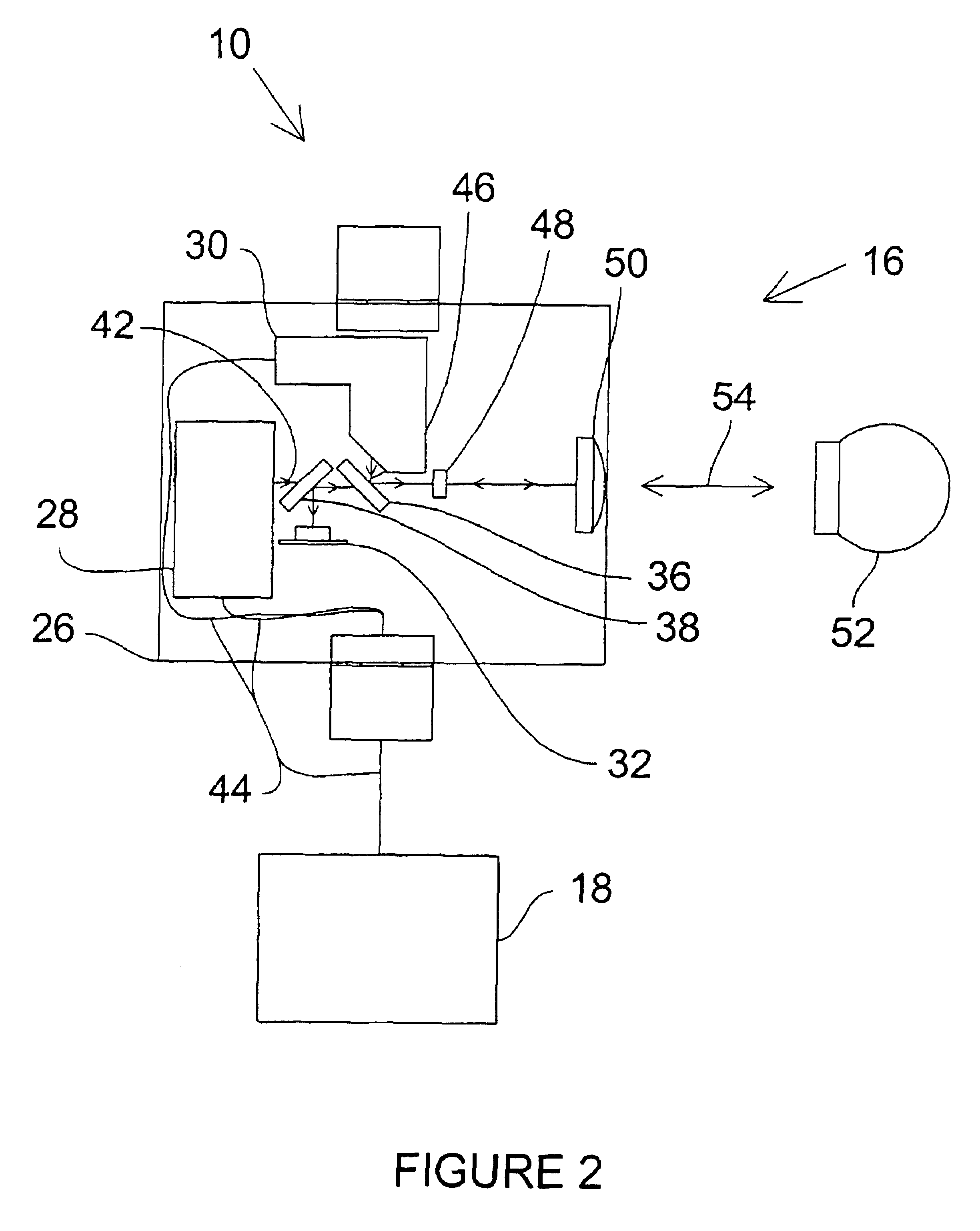
Reference will now be made in detail to the preferred embodiments of the present invention, examples of which are illustrated in the accompanying drawings. The present invention provides an ADM that uses a chopper to improve measurement stability and, if incorporated into a laser tracker, to reduce R0 error.

Exemplary Laser Tracker Characteristics

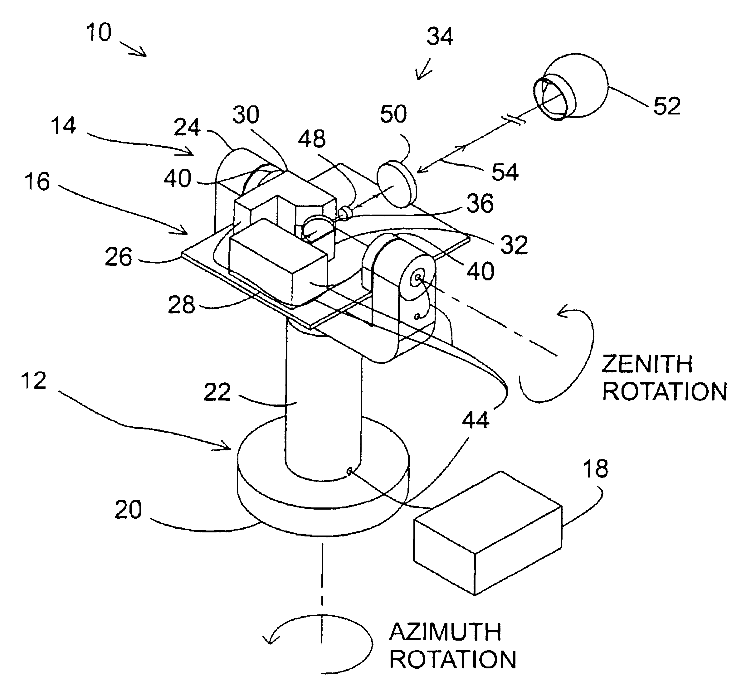
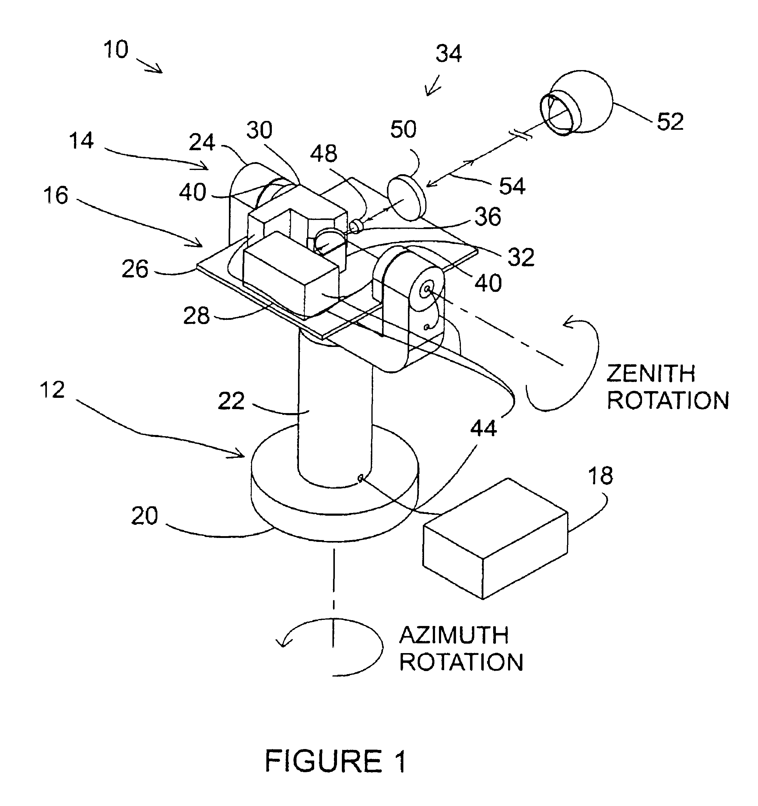
Referring now to FIG. 1, a perspective view of an exemplary laser tracker 10 sending a laser beam to an SMR is illustrated. The exemplary laser tracker generally comprises an azimuth-axis assembly 12, a zenith-axis assembly 14, a payload assembly 16, and an auxiliary assembly 18. An exemplary azimuth-axis assembly 12 comprises a base mount 20, an azimuth-axis outer structure 22, an azimuth-axis inner shaft (not shown), azimuth-axis bearings (not shown), an azimuth-axis motor (not shown), and an azimuth-axis angular encoder (not shown). Various exemplary features of the azimuth-axis assembly 12 are described below. The base mount 20 may be de...


PUM


Abstract

An absolute distance measurement device is provided, including reference and measurement laser signal paths, comprising a laser source providing a laser signal and a chopper assembly, comprising a rotatable surface defining at least one aperture provided through a portion of the rotatable surface; wherein the laser signal is directed to different points on the rotatable surface of the chopper assembly such that as the rotatable surface is rotated, the aperture selectively permits transmission and selectively prevents transmission of each of said at least two laser signal paths.

Description

BACKGROUNDGenerally, an absolute distance meter (ADM) is a device that determines the distance to a remote target. It does this by sending laser light to the target and then collecting light that the target reflects or scatters. An ADM may be used to measure distances in one dimension or it may be attached into a more complex device having the ability to measure quantities corresponding to additional dimensions (degrees of freedom).An example of such a device is a laser tracker, which measures three-dimensional spatial coordinates. The laser tracker sends a laser beam to a retroreflector target that is held against a surface of interest or placed into a fixed nest. The most common type of retroreflector target is the spherically mounted retroreflector (SMR), which may comprise a cube-corner retroreflector mounted within a sphere with the vertex of the cube-corner at the sphere center.A gimbal mechanism within the laser tracker may be used to direct a laser beam from the tracker to t...

Claims


Application Information

Patent Timeline
IPC IPC(8): G01S17/36G01S17/00G01S7/481G01S17/32G01S7/48
CPCG01S7/4811G01S7/4812G01S17/36G01S17/32G01S7/4818
Inventor BRIDGES, ROBERT E.
Owner FARO TECH INC
Learn More