Laser anemometer

a laser anemometer and laser technology, applied in the field of laser anemometers, can solve the problem of much more space in proximity

Inactive Publication Date: 2005-01-25
THALES SA
View PDF14 Cites 15 Cited by
  • Summary
  • Abstract
  • Description
  • Claims
  • Application Information

AI Technical Summary

Benefits of technology

Another advantage is the total absence of electrical components or connections on this panel, which makes it insensitive to electromagnetic interference.
For an anemometer which measures along a plurality of axes, use will be made of a plurality of panels each carrying one set of emission and reception optics and one optical mixer. The laser sources are remotely located and connected to each of the panels by at least one respective optical fibre, and the detectors (which are not necessarily at the same position as the sources) are each connected to one of the panels by at least one respective optical fibre. The panels may be geographically separated from one another—for example, in an aircraft, a first panel on the port side, another on the starboard side and the third high up in the cabin. However, they may also be carried by the same structure, for example placed in the front of the aircraft, this structure then preferably having orientation adjustment means making it possible to adjust the orientations of each set of emission-reception optics to a desired value with respect to the structure (and therefore with respect to the aircraft).

Problems solved by technology

With the old architectures, much more space was needed in proximity to the outer surface of the aircraft, precisely where this space is often unavailable.

Method used


Image

  • Laser anemometer
  • Laser anemometer
  • Laser anemometer

Examples


Embodiment Construction

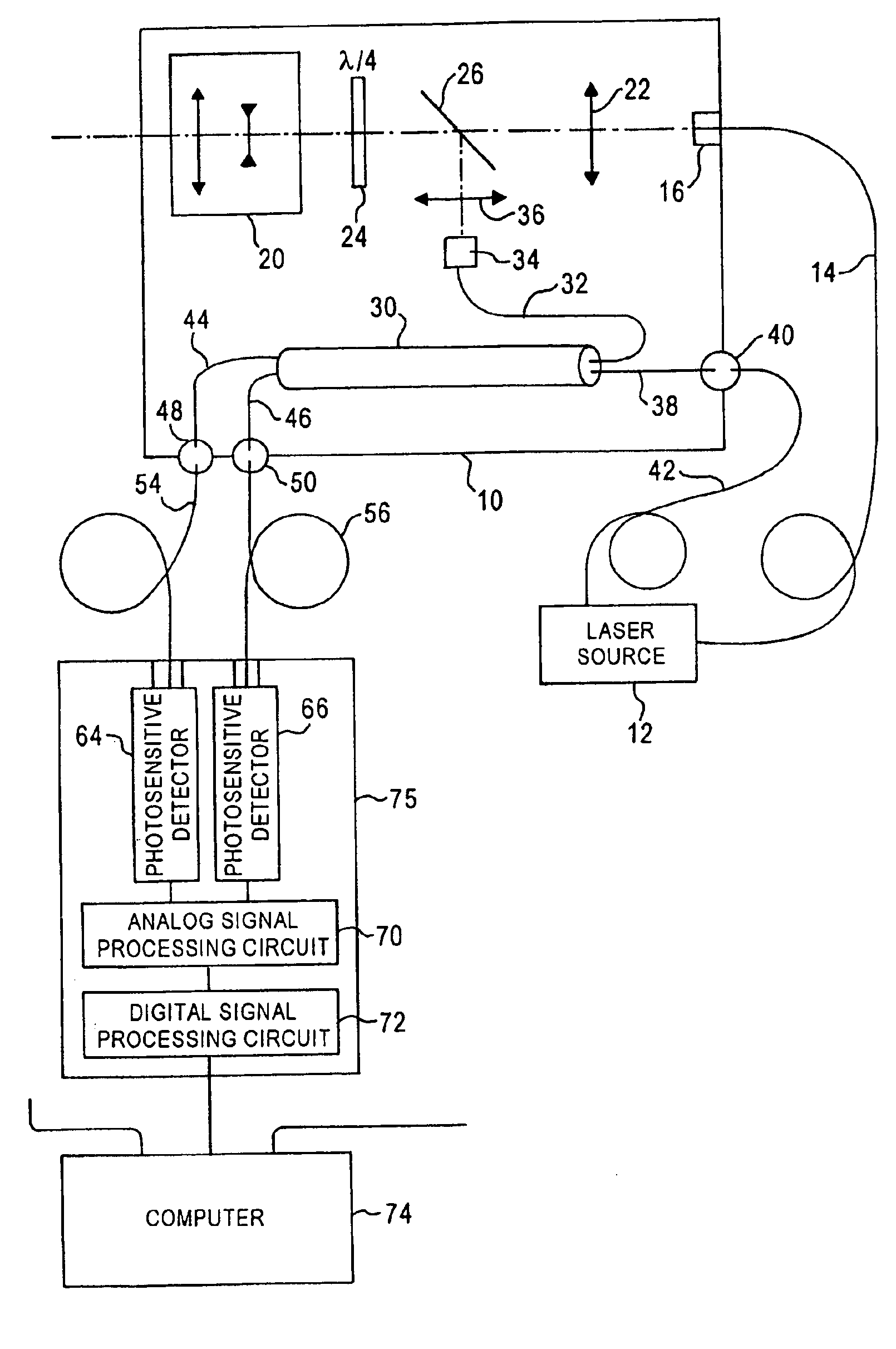
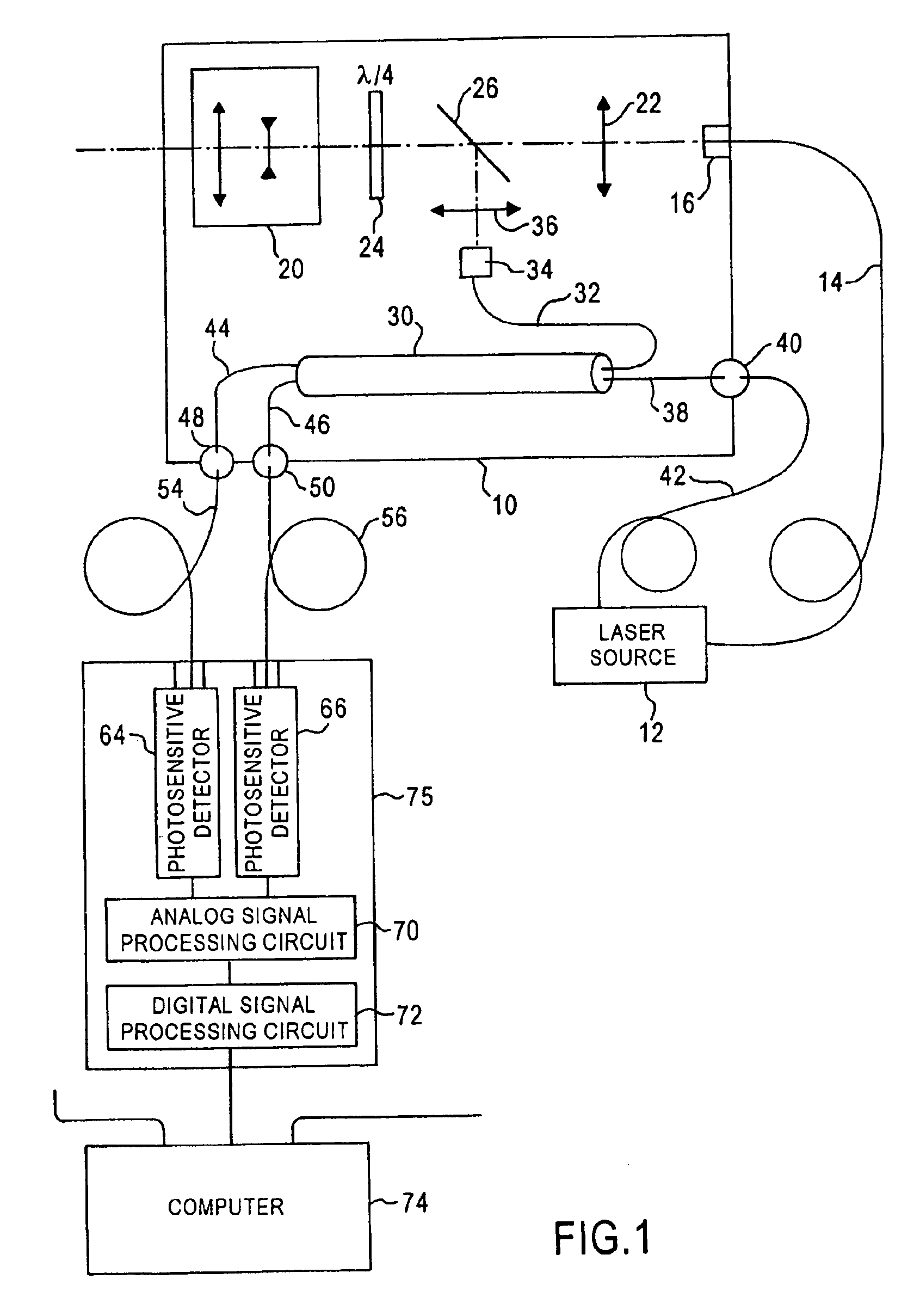
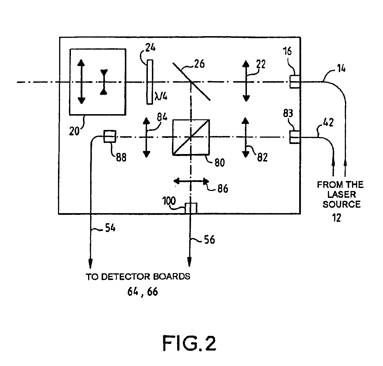
The laser anemometry system includes a support panel 10 carrying the optics for emission and reception of a laser beam, but not carrying the laser source from which this beam originates. The laser source 12 is remotely located so as to be situated at a different position, and it is connected to the panel by an optical fibre 14. This fibre is preferably of the single-mode and polarization-preserving type in order to conserve the polarization of the beam, the polarization being useful in particular for splitting the emission beam and the return beam inside the emission and reception optics (this splitting is carried out by a birefringent plate, as will be seen).

The fibre end connected to the panel is carried by a holding head 16, preferably with means (not shown) for adjusting the position of this head on the panel.

The emission and reception optics comprise the elements conventionally needed for producing a laser beam focused at a distance of about fifty metres. These optics have been...


PUM


Abstract

The present invention relates to a laser anemometer making it possible to determine the relative velocity between the anemometer and an ambient medium. The architecture of the anemometer includes a laser source, emission and reception optics for focusing a laser beam onto a measurement zone containing particles in suspension in the ambient medium and for receiving the radiation back-scattered by the particles. It also includes an optical mixer for mixing the received radiation and reference radiation representing the radiation emitted by the source, and a detector at the output of the mixer. The relative velocity between the anemometer and the ambient medium is determined by computation on the basis of the Doppler effect generated by the radiation and detected by the detector. The laser source is located remotely from a common support which carries the optical emission and reception system as well as the mixer. It is connected to this common support by at least one optical fiber. The detector is also remotely located and connected by at least one optical fiber. The main emission channel of the emission and reception system carried by the support is produced with the aid of unguided optics.

Description

RELATED APPLICATIONThe present application is based on, and claims priority from, French Application Serial No. 01 / 03930, filed Dec. 11, 2001, the disclosure of which is hereby incorporated by reference herein in its entirety.FIELD OF THE INVENTIONThe present invention relates to laser anemometers, that is to say instruments for measuring the velocity of air or velocity with respect to air, which use the following principle: illumination at a distance, using a beam of generally infrared laser light, of a region in space containing particles or dust in suspension (which are naturally present or intentionally injected into this region, and also referred to as aerosols), reflection of the light from the particles, optical detection of the beam reflected towards the source, and electronic processing in order to determine by calculation a relative velocity between the source-detector assembly, on the one hand, and the particles, on the other hand.BACKGROUND OF THE INVENTIONLaser anemomet...

Claims


Application Information

Patent Timeline
Patent Type & Authority Patents(United States)
IPC IPC(8): G01P5/26G01P5/00G01S17/58G01S17/00G01S7/481
CPCG01P5/26G01S17/58G01S7/4812G01S7/4818
Inventor BRUEL, CHRISTINECOMBE, HUBERT
Owner THALES SA
Why Eureka
Try Eureka