Magnetic head device and recording reproducing apparatus

a head device and recording technology, applied in the direction of light beam reproducing, instruments, maintaining head carrier alignment, etc., can solve the problems of inability to make thin optomagnetic recording/reproducing apparatus, etc., to achieve excellent effects, reduce cost, and reduce the size of recording/reproducing apparatus

Inactive Publication Date: 2005-01-25
PANASONIC CORP
View PDF46 Cites 9 Cited by
  • Summary
  • Abstract
  • Description
  • Claims
  • Application Information

AI Technical Summary

Benefits of technology

It is an object of the present invention I to solve these problems of the prior art and to provide a magnetic head device that maintains a structure with excellent shock resistance and achieves a thinner optomagnetic recording / reproducing apparatus.
With the first to the third structures described above, it is possible to provide a recording / reproducing apparatus having excellent effects as follows. Clearance that was conventionally necessary for preventing a contact can be reduced, thus achieving a thinner and smaller recording / reproducing apparatus. At the same time, since high accuracy mechanism is not necessary, it is possible to achieve lower cost.

Problems solved by technology

When the resilient force is too large, the sliding friction between the head main body and the optomagnetic disk increases, and may result in considerable wear of the head main body and the optomagnetic disk.
Consequently, there has been a problem in that the optomagnetic recording / reproducing apparatus cannot be made thinner.
Consequently, there had been a problem in that the optomagnetic recording / reproducing apparatus cannot be made thinner.
This hinders the optical head device and the magnetic head device from moving in the y-axis direction in terms of an electric power and grade.
Also, when the magnetic head main body 351 glides in contact over the reproducing cartridge 304, traces of slide and wear are left on a label surface, thereby deteriorating the grade.
However, the conventional recording / reproducing apparatus described above had the following problems.
However, the conventional structure described above cannot reduce the values of distances h1 and h2 because of the large variation of the fastening member 353 and the magnetic head main body 351 in the z-axis direction.
Thus, it was difficult to reduce the value of the distances h1 and h2 because of its design, resulting in the larger apparatus.
In addition, thinner apparatus were produced by means of improving the mechanical accuracy, leading to a cost increase.

Method used


Image

  • Magnetic head device and recording reproducing apparatus
  • Magnetic head device and recording reproducing apparatus
  • Magnetic head device and recording reproducing apparatus

Examples


embodiment i-1

(Embodiment I-1)

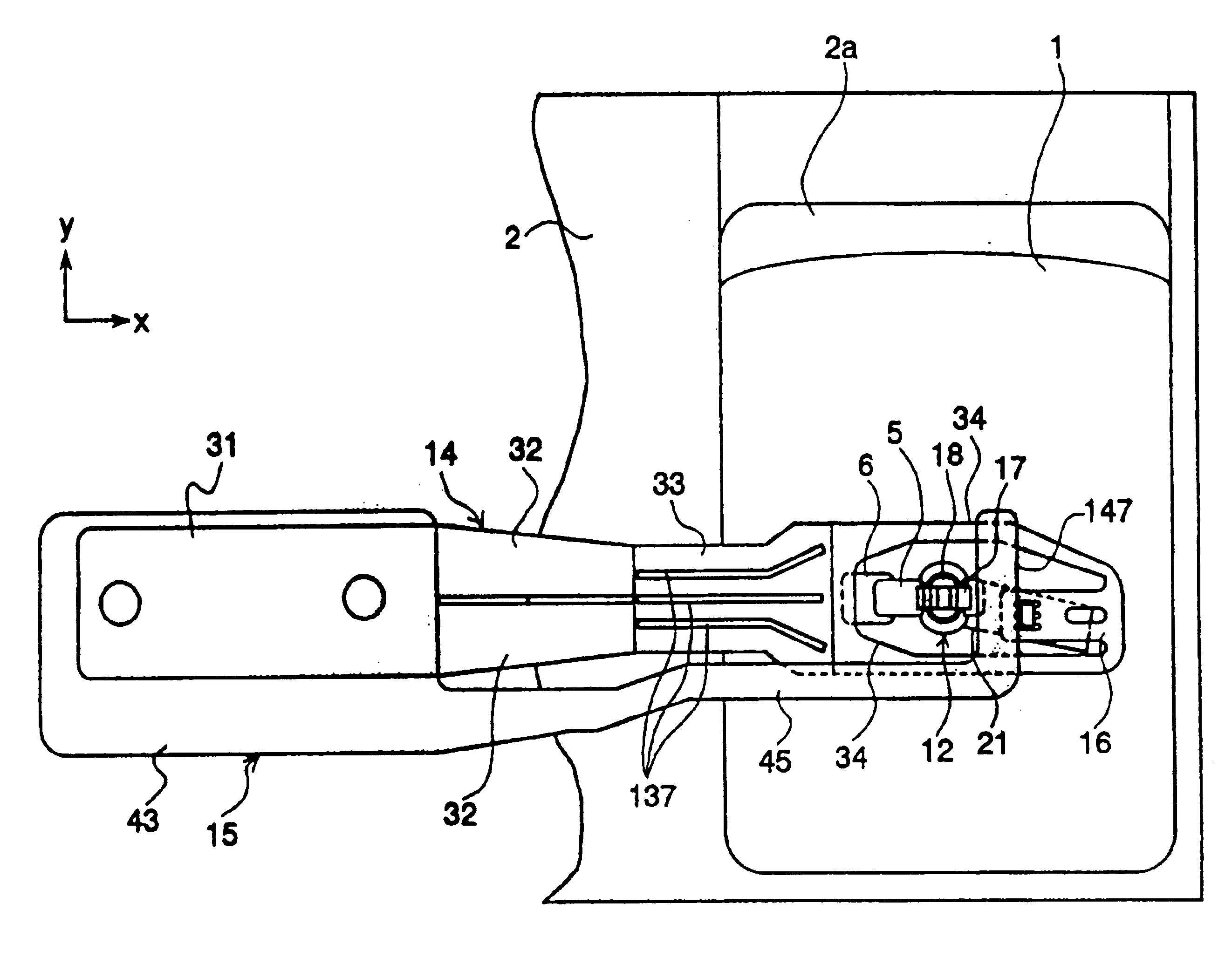
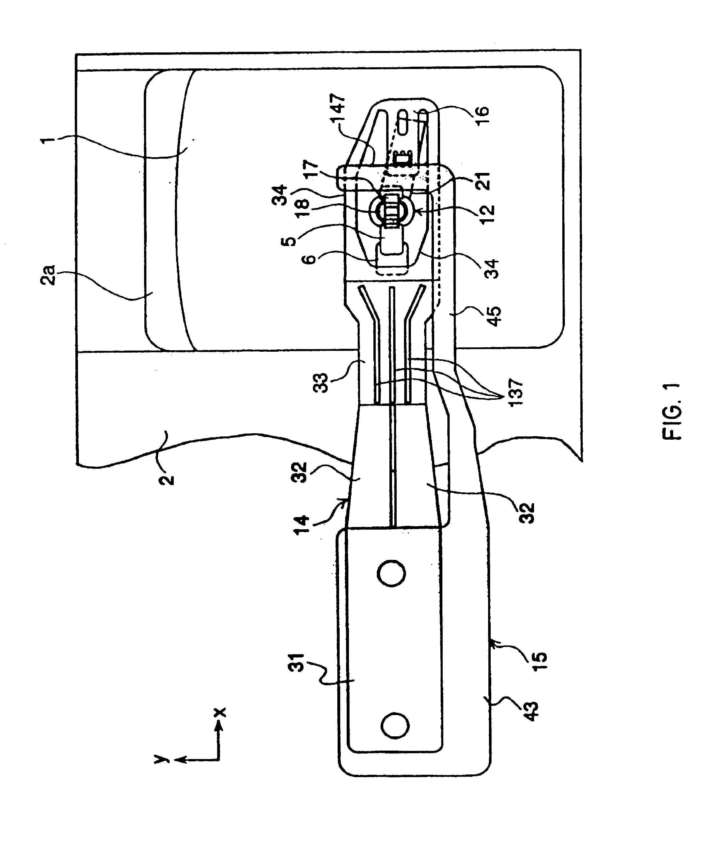
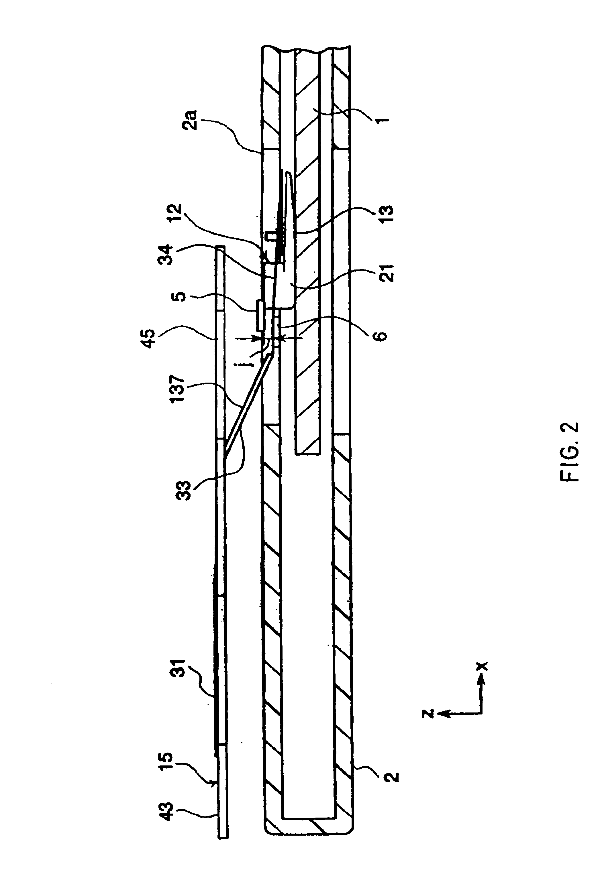
FIG. 1 is a plan view of a magnetic head device of an embodiment I-1 of the present invention I, FIG. 2 is a side view of the magnetic head device shown in FIG. 1, FIG. 3 is a sectional side view of a main portion of a head main body of the magnetic head device shown in FIG. 1, FIG. 4 is an enlarged perspective view of a first holding portion and a second holding portion of the magnetic head device shown in FIG. 1, FIG. 5 is a side view showing a state of the magnetic head device shown in FIG. 1 not in use, and FIG. 6 is a side view showing a reaction when a shock is applied to the magnetic head device not in use.

The same reference numerals are given to components having the same functions as in the conventional examples shown in FIGS. 23 to 27, and detailed descriptions thereof are omitted here.

In FIGS. 1 to 6, numeral 14 denotes a suspension, which is made of a thin spring material such as SUS304 or BeCu. The suspension 14 has a planar attaching portion 31 at one e...

embodiment i-2

(Embodiment I-2)

The following is a description of a magnetic head device in accordance with the embodiment I-2, with reference to FIGS. 7 to 10.

FIG. 7 is a plan view of the magnetic head device of the embodiment I-2 of the present invention I, FIG. 8 is a side view of the magnetic head device shown in FIG. 7, FIG. 9 is an enlarged perspective view of first holding portions and a second holding portion of the magnetic head device shown in FIG. 7, and FIG. 10 is a side view showing a reaction when a shock is applied to the magnetic head device not in use.

The magnetic head device of the embodiment I-2 is different from that of the embodiment I-1 in that two first holding portions 7 are disposed in a head main body 12, so as to be spaced away from each other with a predetermined distance in the vertical direction (the direction perpendicular to the surface of an optomagnetic disk 1), and a second holding portion 6 that is disposed on the side of the connected end of the second elastic p...

embodiment i-3

(Embodiment I-3)

The following is a description of a magnetic head device in accordance with the embodiment I-3, with reference to FIGS. 11 to 13.

FIG. 11 is a plan view of the magnetic head device of the embodiment I-3 of the present invention I, FIG. 12 is a side view of the magnetic head device shown in FIG. 11, and FIG. 13 is an enlarged perspective view of first holding portions and a second holding portion of the magnetic head device shown in FIG. 11.

The magnetic head device of the embodiment I-3 is different from that of the embodiment I-2in the following points. That is, first holding portions 8 are disposed in the upper and lower parts of a head main body 12, and convex portions 8a protruding toward the direction perpendicular to a recording surface of an optomagnetic disk 1 are disposed on the opposing sides of the upper and lower holding portions 8. On the side of the connected end of the second elastic portion 34, a second holding portion 9 having a through hole 9a is disp...


PUM

PropertyMeasurementUnit
distanceaaaaaaaaaa
distances h1aaaaaaaaaa
distanceaaaaaaaaaa

Abstract

A head main body (12) is supported at a free end of a cantilevered suspension (14). The head main body (12) has a first holding portion (5) that is substantially in parallel to an information recording medium (1), and the suspension (14) has a second holding portion (6) that is substantially in parallel to the information recording medium (1) and is located near the free end of the suspension (14). When a magnetic head device is not used, the head main body (12) is spaced away from the information recording medium (1). At this time, when an external shock is applied, the first holding portion (5) and the second holding portion (6) contact each other, thereby preventing a permanent deformation of the suspension (14). It is possible to reduce a displacement amount against a shock when the head main body (12) is spaced away from the information recording medium (1). Consequently, a spacing amount of the magnetic head main body (12) can be reduced. As a result, it becomes possible to make a thinner optomagnetic recording / reproducing apparatus.

Description

TECHNICAL FIELD[The invention I]The present invention I relates to a magnetic head device for applying a magnetic field to an information recording medium in a recording / reproducing apparatus for optomagnetic disks such as mini disks (referred to as “MD”s in the following) or optomagnetic data filing systems.[The invention II]The present invention II relates to a magnetic head device for applying a magnetic field to an information recording medium in a recording / reproducing apparatus for optomagnetic disks such as mini disks (referred to as “MD”s in the following) or optomagnetic data filing systems.[The invention III]The present invention III relates to a structure of a recording / reproducing apparatus for recording information on an information recording medium or reproducing information recorded thereon by interactions mainly with the information recording medium, more specifically effects such as optical, thermal and magnetic field effects. In particular, the present invention II...

Claims


Application Information

Patent Timeline
Patent Type & Authority Patents(United States)
IPC IPC(8): G11B11/105G11B11/00G11B21/22G11B5/55G11B5/54G11B5/596G11B5/48
CPCG11B5/54G11B5/5552G11B5/5582G11B21/22G11B11/1055G11B11/10558G11B11/1058G11B5/596
Inventor MURAKAMI, YUTAKAMIZUNO, OSAMU
Owner PANASONIC CORP
Why Eureka
Try Eureka