Wireless communication data rate control prediction method and system

a technology of data rate control and wireless communication, applied in the field of wireless communication, can solve the problems of underutilization of base station transmissions, less reliable transmissions, and low data rate use, and achieve the effect of improving overall prediction accuracy and less pronounced fluctuations

Inactive Publication Date: 2005-01-25
QUALCOMM INC
View PDF3 Cites 29 Cited by
  • Summary
  • Abstract
  • Description
  • Claims
  • Application Information

AI Technical Summary

Benefits of technology

In one embodiment, the invention includes generating a predicted SINR of a signal to be received by a mobile station by first obtaining a measured SINR value, typically based on each pilot burst received from the base station, then subtracting a separately estimated periodic mean SINR component from this measured SINR value to obtain an intermediate SINR value, then performing an intermediate prediction on this intermediate SINR process, and finally adding the effect of the periodic mean SINR appropriately to the resulting intermediate prediction to obtain a final prediction. This way, the overall prediction accuracy is improved, because the intermediate SINR process that is fed to the intermediate predictor typically has less pronounced fluctuations than the measured SINR process since its time-varying mean is taken out. The invention may also include methods to detect the presence of a periodic mean SINR component in the measured SINR process based on which the above described method can be turned on or off. The invention may also include methods for dynamically reducing the final predicted SINR value to meet certain packet error rate requirements. The invention also includes certain methods of estimating the periodic mean SINR.

Problems solved by technology

At lower SINR levels, transmissions are less reliable and lower data rates are used.
However, when the SINR fluctuations become too large, or the SINR varies too quickly, even the use of a predictor can lead to a requested data rate, which will either underutilize base station transmissions or otherwise lead to error.

Method used


Image

  • Wireless communication data rate control prediction method and system
  • Wireless communication data rate control prediction method and system
  • Wireless communication data rate control prediction method and system

Examples


Embodiment Construction

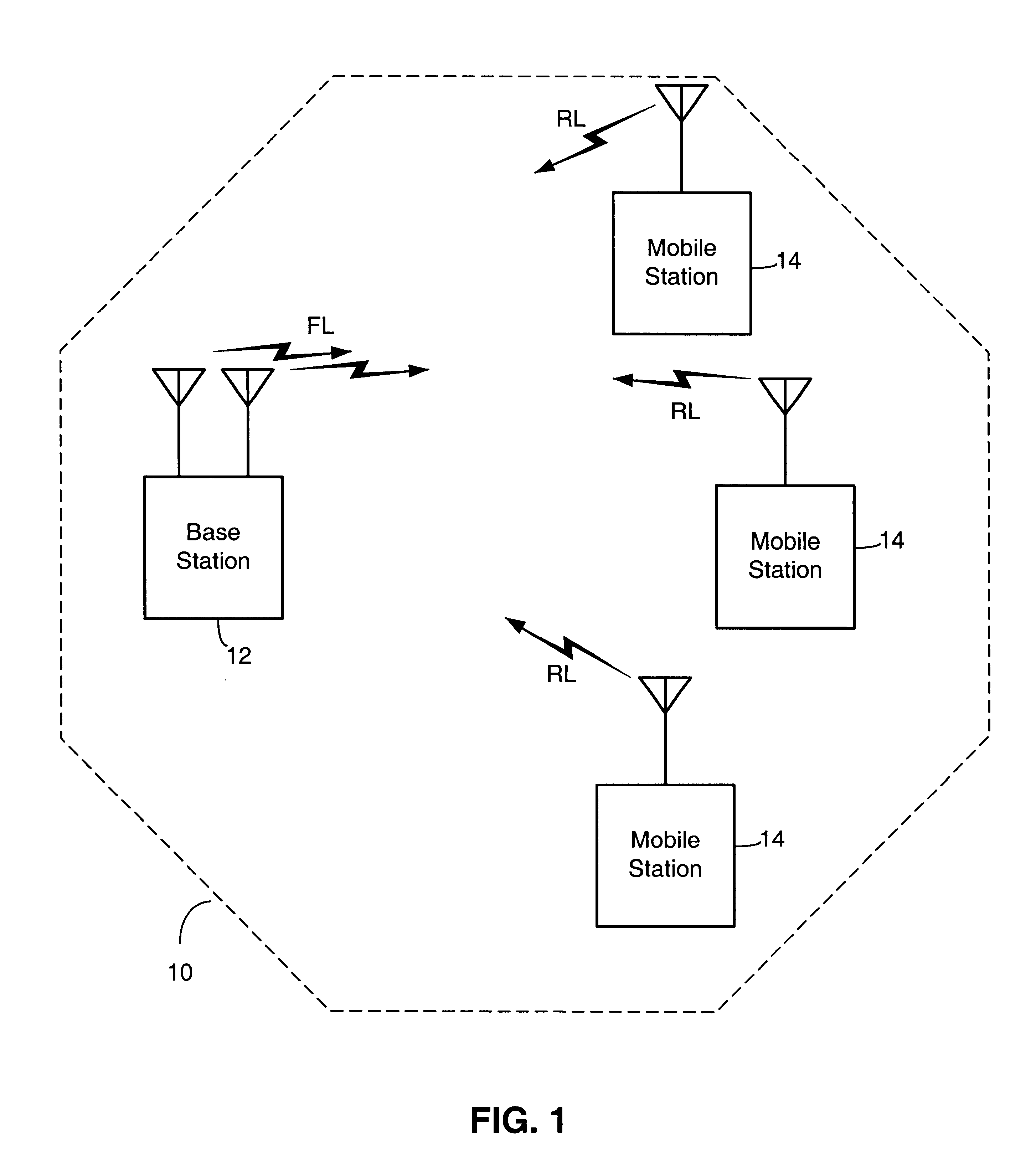
Referring to FIG. 1, a diagram illustrating a wireless communication system in one embodiment is shown. In this system, a base station 12 and several mobile stations 14 are depicted. Base station 12 transmits data to mobile stations 14 via what is referred to herein as the forward link (FL). Mobile stations 14 transmit data back to base station 12 via what is referred to herein as the reverse link (RL). Mobile stations 14 are within the sector for which base station 12 has responsibility. Mobile stations may move within the sector, or they may move out of the sector associated with base station 12 and into a sector associated with another base station.

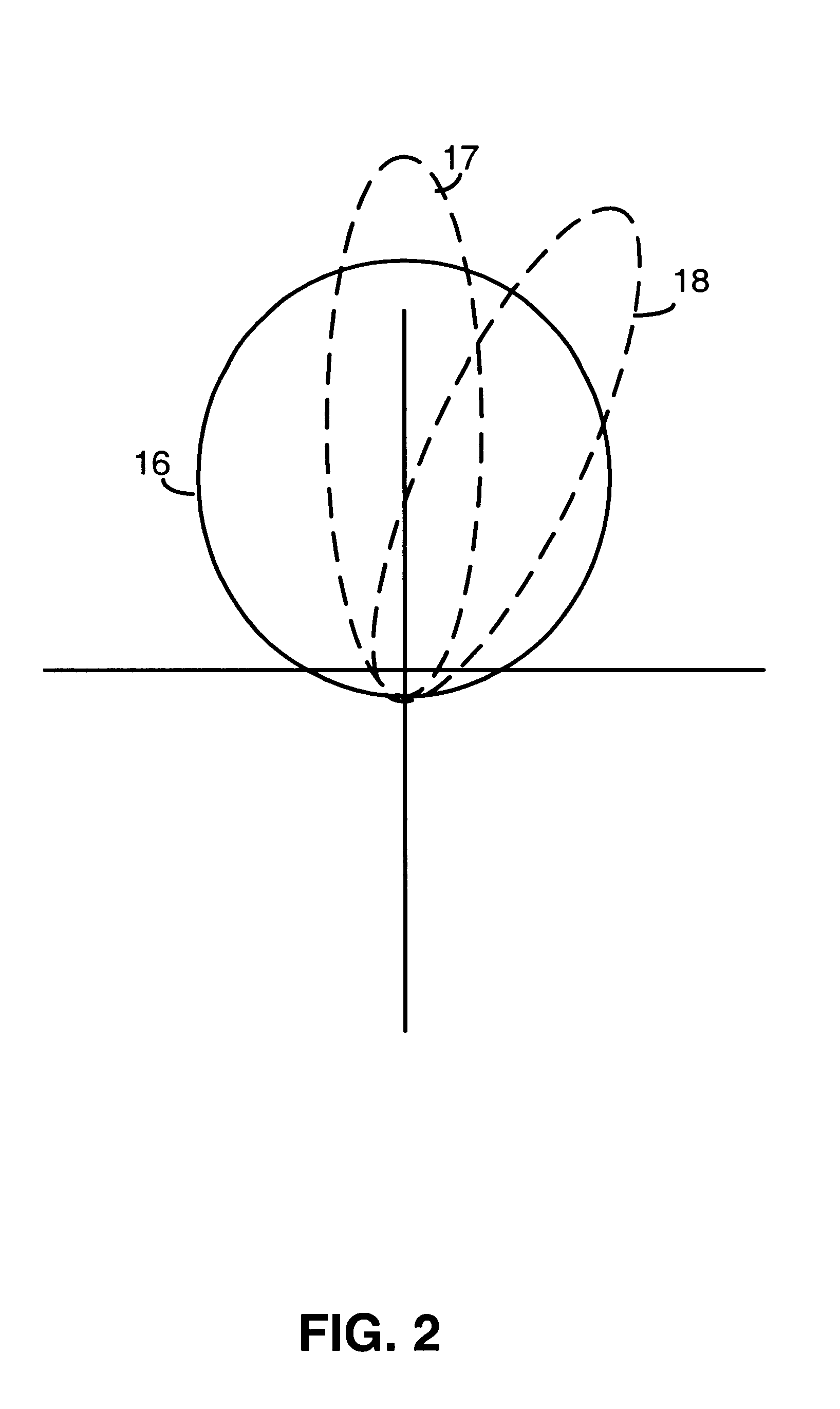
In one embodiment, the base station 14 may be configured to perform beamforming operations (such as in the FPC scheme described earlier) through the use of two antennas. (“Beamforming” is used herein to refer to the forming of a directional antenna gain pattern for the forward link of a base station.) One of the antennas transmits a da...


PUM


Abstract

Systems and methods for predicting the signal-to-interference-and-noise ratio (SINR) of the signal to be received by a mobile station transmitted from a base station in a wireless data communications system, for the purpose of forward link data rate control in the presence of partly periodic SINR fluctuations. The invention involves determination of a periodic mean SINR component in the received SINR process, and upon such determination the activation of a method which comprises a periodic mean SINR estimator, a subtractor which subtracts the periodic component from the received SINR process to produce an intermediate SINR process, a generic predictor which may be used to perform predictions on the intermediate SINR process, an adder which adds back an appropriate mean value to the intermediate SINR prediction. The resulting final SINR prediction is then used for rate selection.

Description

FIELD OF THE INVENTIONThe invention relates generally to wireless communications, and more particularly, to a mobile station data rate control predictor.BACKGROUNDWireless communication systems are divided into a number of geographic sectors. At least one base station is associated with a sector. Mobile stations within the sector can communicate with other mobile stations, within the same or a different sector, or with external networks, via the base station. At any given time, each mobile station typically communicates with only a single base station, however the base station must be able to communicate with all of the mobile stations within its sector.Some base stations employ a scheduler to allocate resources among their serving mobile stations. One type of scheduler that may be used is referred to as a proportional fair scheduler. This scheduler is designed to balance fairness of service among the mobile stations against the maximization of overall throughput of data by the base...

Claims


Application Information

Patent Timeline
Patent Type & Authority Patents(United States)
IPC IPC(8): H04L1/00H04L1/20
CPCH04L1/0002H04L1/20H04L1/0036H04L1/0025
Inventor GURELLI, MEHMET IZZETETKIN, RAUL HERNAN
Owner QUALCOMM INC
Why Eureka
Try Eureka