
Apparatus for blowing and removing glass containers

a glass container and glass technology, applied in glass making apparatus, transportation and packaging, manufacturing tools, etc., can solve problems such as disadvantages in machine timing

Inactive Publication Date: 2005-02-01
OWENS-BROCKWAY GLASS CONTAINER INC
View PDF19 Cites 16 Cited by
  • Summary
  • Abstract
  • Description
  • Claims
  • Application Information

AI Technical Summary

Benefits of technology

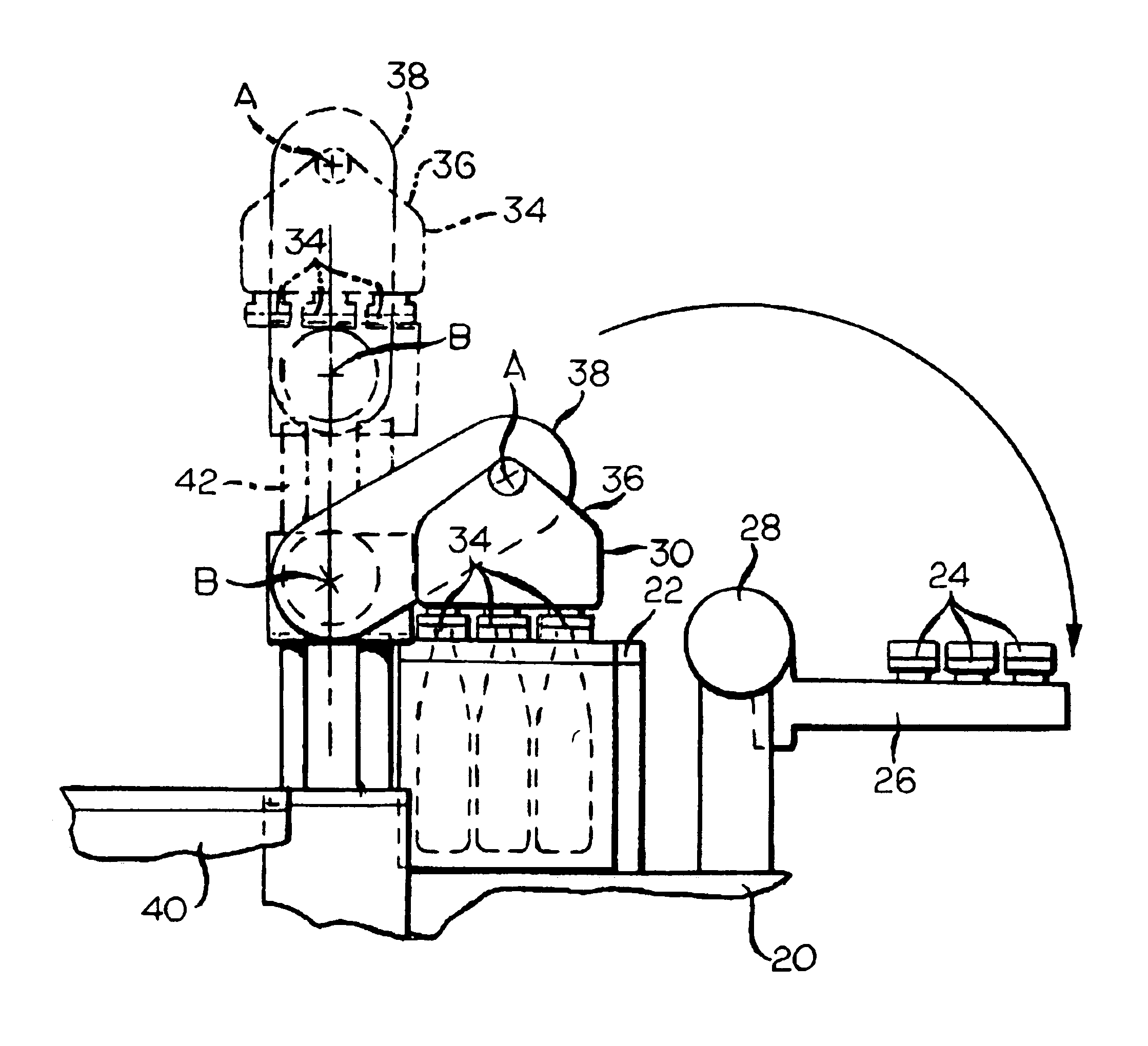
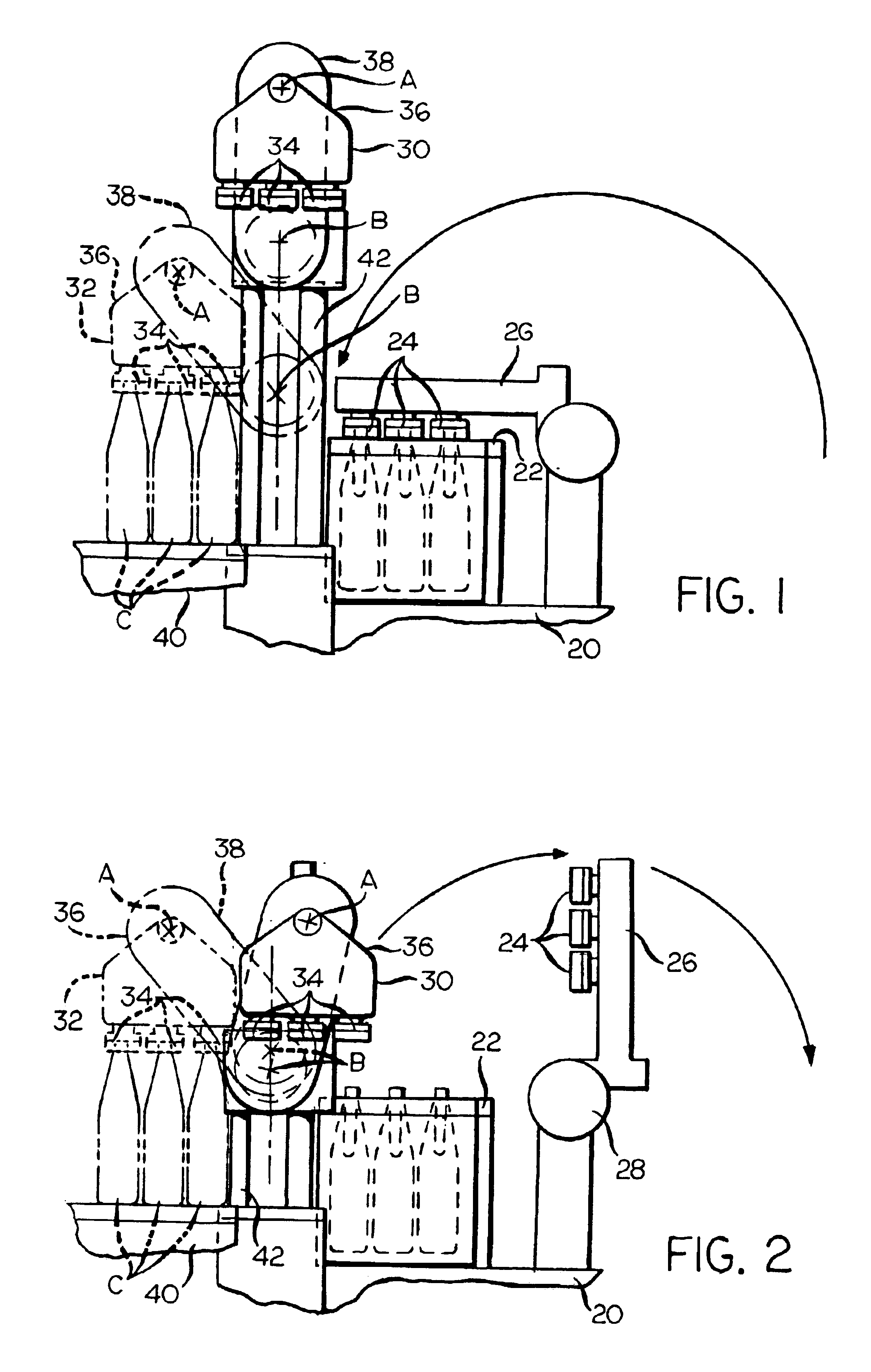
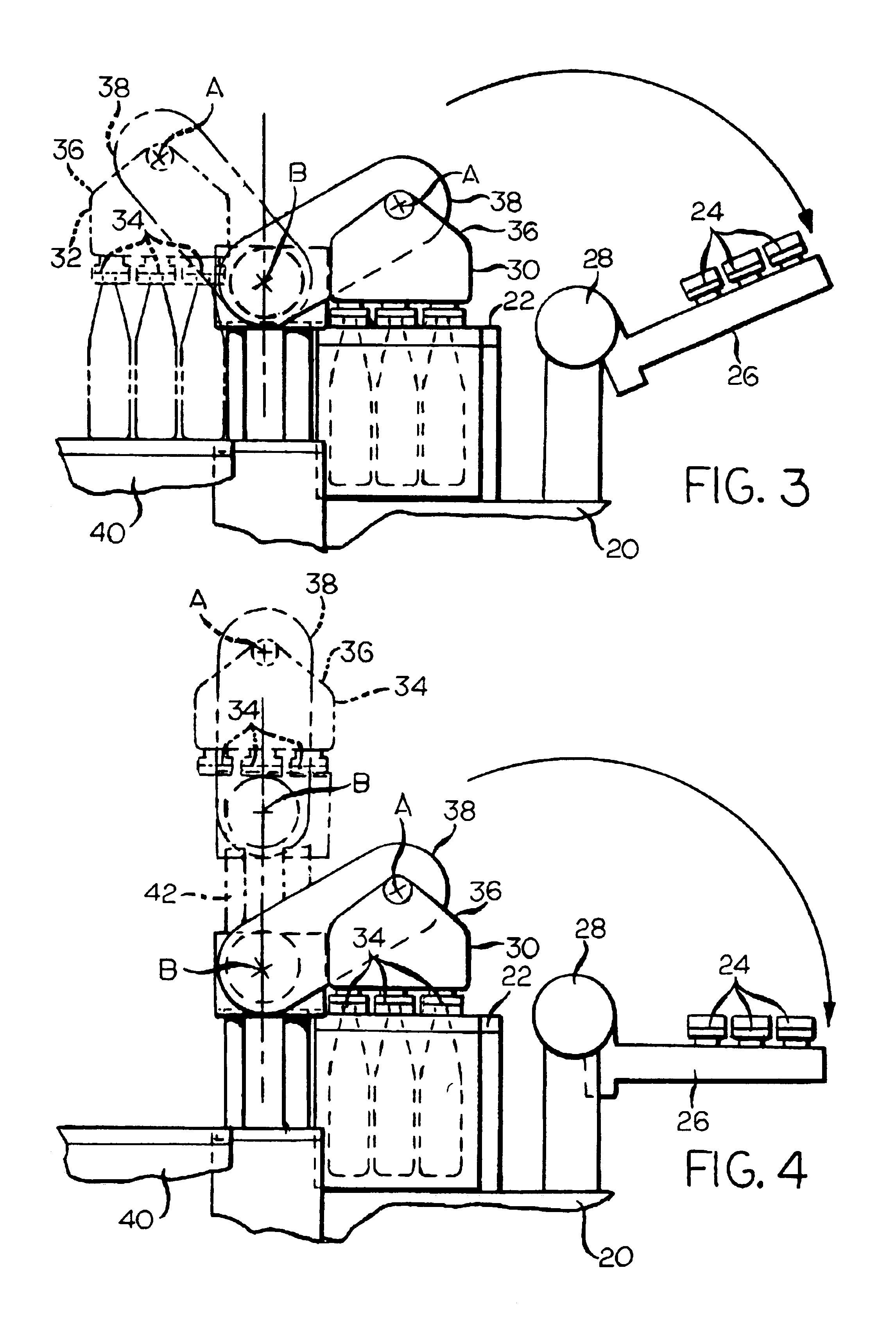
According to the present invention there is provided a combined blowhead / takeout mechanism for an I.S. glass container forming machine, and a method for blowing glass containers in blow molds of such a glass container forming machine and removing blown containers from such molds. The apparatus includes a container finish engaging chuck for each of the containers that are simultaneously formed at a section of the I.S. machine, and each chuck includes a plurality, preferably three, of circumferentially spaced-apart elements that move in and out, in unison, to engage a container by its finish. In this way, the container may be engaged by the chuck while the split molds in which the container is being blown remain closed, to thereby permit the container to be removed for transfer to a deadplate of I.S. machine immediately upon the opening of the split molds of the blow molding machine in which the container was formed. This eliminates the lost cycle time of certain prior art takeout devices, such as that of the aforesaid '419 patent, which require that the split mold be opened before a container with a transfer bead can be engaged by the takeout device.
In a preferred embodiment of the present invention, a pair of combined blowhead / takeout mechanisms is provided at each section of an I.S. machine. The combined mechanisms are timed to operate alternatively so that one combined mechanism can be positioned to blow containers in the blow molds of the machine while the other combined mechanism is positioned, after depositing blown containers on the machine deadplate, to immediately return to the blow molds to begin a repeat of the blow molding cycle. This eliminates lost cycle time that can arise in an I.S. machine with only a single blowhead at each machine section, as the blowing cycle can not begin until the blowhead returns from having deposited blown containers on the machine's deadplate. To avoid collision of the separate combined mechanisms during operation, the pivot axis of the pivoting arm of each combined mechanism is moveable in a vertical plane, so that the incoming combined mechanism can be positioned at an elevation above that reached by the outgoing combined mechanism during its pivoting motion to transfer blown containers from the blow molds to the machine deadplate. The use of a pair of combined blowhead / takeout mechanisms in this manner improves forming cycle time because it ensures that a combined blowhead / takeout mechanism will be positioned at the blow molds when the molds close around parisons that were transferred to the molds without the need to wait for the return of a blowhead from the machine deadplate after depositing previously blown containers thereon.

Problems solved by technology

The requirement that blow molds be opened before the blown container can be grasped by tongs is a machine timing disadvantage for reasons explained in the aforesaid '488 B1 patent.

Method used


Image

  • Apparatus for blowing and removing glass containers
  • Apparatus for blowing and removing glass containers
  • Apparatus for blowing and removing glass containers

Examples


Embodiment Construction

As is shown schematically in FIGS. 1-6, an I.S. machine section 20, shown fragmentarily, is provided with a set of blow molds 22 in which containers C are blown from blanks or parisons P of a glass composition at a suitable high temperature to be formable by blowing. FIGS. 1-6 show three containers being formed in each set of blow molds, but it is to be understood that the invention is suited for use in I.S. machines that are designed to simultaneously produce as many as four containers at each machine section (a “quad” machine), or even as few as one container at each such section. In any case, as is understood in the art, each set of blow molds 22 is made up of an opposed set of split molds that periodically open and close with respect to each other by counteroscillating or counterrectilinear motions to define, when closed, a cavity for each container C to be formed therein.

The parisons P to be formed into the containers C in the mold set 22 are transferred thereto from a blank mo...


PUM


Abstract

Vertically aligned first (30) and second (32) combined blowhead and takeout mechanisms are provided to sequentially blow glass parisons (P) into containers (C) in a mold set (22) and to transfer blown containers to a deadplate (40) of a glass containing forming machine (20). Each of the combined mechanisms is pivotally suspended about an axis A from a carrier arm (36) that is pivotally attached to an end of an oscillating arm (38), an opposed end of which is pivoted about an axis (B). The axis (B) of each combined blowhead and takeout mechanism is periodically raised and lowered to permit the other combined blowhead and takeout mechanism to oscillate therebeneath, to thereby permit overlapping cycles between the blowhead and takeout mechanisms. Each blowhead and takeout mechanism is provided with a chuck or tong assembly (54) to engage or release each container by its finish (F). Each tong assembly has a plurality of tong elements (74) that are simultaneously moved radially in or out by oscillation of a cam (50) that has a non-circular slot (78) in which a pin (76) carried by each tong element rides.

Description

FIELD OF THE INVENTIONThis invention relates to a method of and an apparatus for blowing glass containers in molds of a glass container forming machine and for removing blown containers from such molds. More particularly, this invention relates to a method of and an apparatus for blowing glass containers in blow molds of an I.S. (individual section) glass container forming machine, and for thereafter removing blown containers from such molds and transferring the blown containers to a deadplate of the machine for cooling and eventual removal for further processing.BACKGROUND OF THE INVENTIONU.S. Pat. No. 3,472,639 (Mumford) and U.S. Pat. No. 4,427,431 (Mumford et al.), which were assigned to a predecessor of the assignee of this application, the disclosure of each of which is incorporated by reference herein, generally describe the manufacture of glass containers by a machine type that is known as an I.S. machine. As taught by such references or as is otherwise known, an I.S. machine...

Claims


Application Information

Patent Timeline
IPC IPC(8): C03B9/00C03B9/447C03B9/36B65D1/00
CPCC03B9/36C03B9/447C03B9/3672C03B9/3618
Inventor LEIDY, D. WAYNEDIFRANK, FRANK J.
Owner OWENS-BROCKWAY GLASS CONTAINER INC
Learn More