Electronic latch apparatus and method

Inactive Publication Date: 2005-02-01
STRATTEC SECURITY
View PDF94 Cites 41 Cited by
  • Summary
  • Abstract
  • Description
  • Claims
  • Application Information

AI Technical Summary

Benefits of technology

Latch assembly operations for placing the control elements in their locked and unlocked states are therefore quickly performed via actuators, and most preferably, by electromagnetic solenoids. Also, the relatively small number of elements (e.g., an actuator, pin, control element, and, if desired, a pawl as described in more detail below) employed to place the latch assembly in its various lock states is a significant advant

Problems solved by technology

In contrast, when the control element moves in a second manner, the control element does not i

Method used


Image

  • Electronic latch apparatus and method
  • Electronic latch apparatus and method
  • Electronic latch apparatus and method

Examples


Embodiment Construction

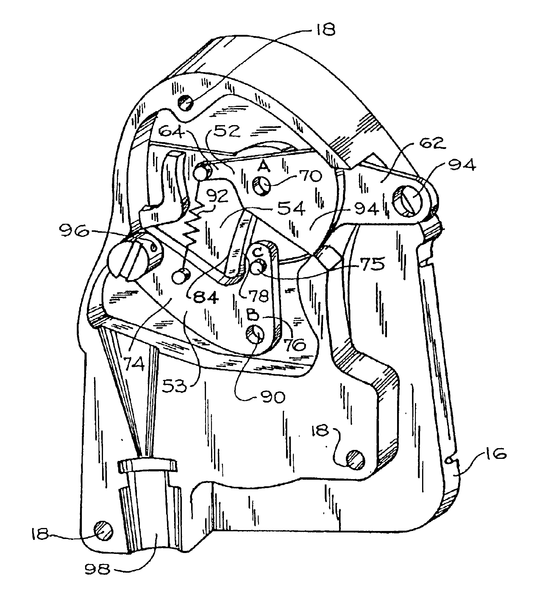
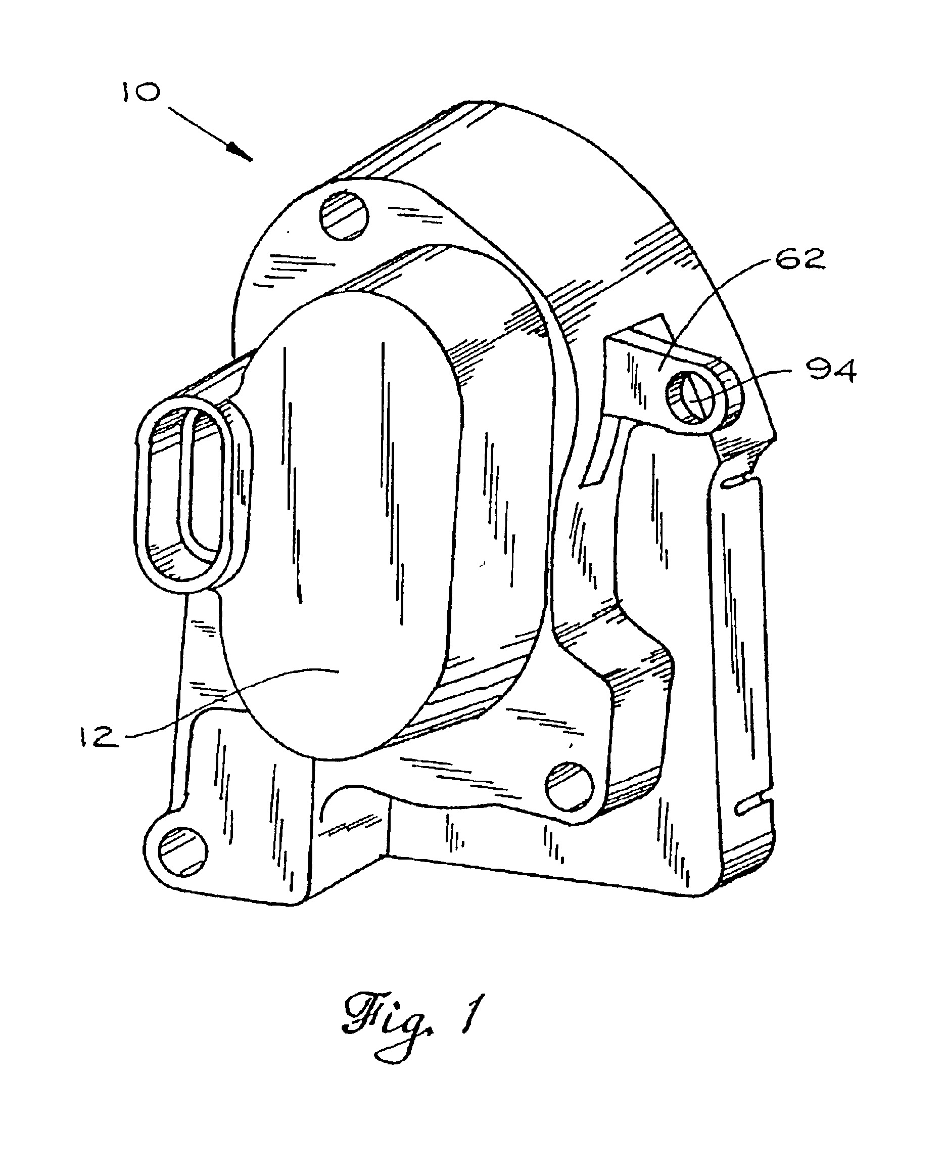
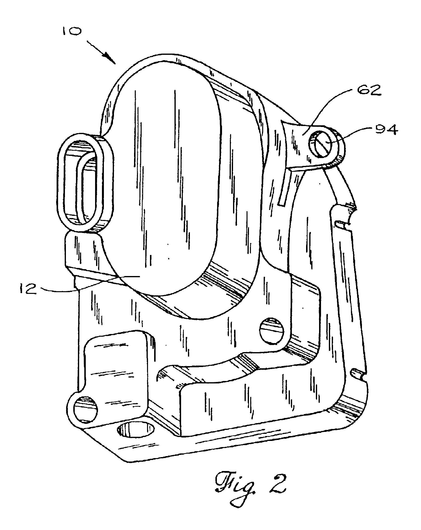
While the latch assembly 10 of the present invention is useful in a variety of applications, it is particularly useful in vehicle applications such as for automotive and truck doors. In such applications, the latch assembly 10 preferably has a front cover 12, a rear mounting plate 14 and a housing 16 which collectively enclose the internal elements and mechanisms of the latch assembly 10. A highly preferred embodiment of the latch assembly 10 is shown in FIGS. 1-3. It should be noted that although the following description is with reference to the latch assembly 10 used in vehicle door applications (where application of the latch assembly 10 can be employed with excellent results), the latch assembly 10 can instead be used in many other applications. In fact, the present invention can be used in any application in which it is desirable to releasably secure one body to another. Such applications can be non-automotive and even in applications not involving doors.

The terms of orientati...


PUM


Abstract

A latch assembly, comprising a control element having a pivot point and an actuator. The actuator has a first position in which the control element is engaged by the actuator for pivotal movement about the pivot point and a second position in which the control element is disengaged by the actuator from pivotal movement about the pivot point. The latch assembly further includes a ratchet arranged and configured for rotation with the control element when the control element is engaged by the actuator and for non-rotation when the control element is disengaged by the actuator. A highly preferred embodiment of the invention includes an automatic unlocking circuit powered by a backup power source.

Description

FIELD OF THE INVENTIONThe present invention relates to latches and latching methods, and more particularly to devices and methods for electronically controlling and switching a latch between latched and unlatched states.BACKGROUND OF THE INVENTIONConventional latches are used to restrain the movement of one member or element with respect to another. For example, conventional door latches restrain the movement of a door with respect to a surrounding door frame. The function of such latches is to hold the door secure within the frame until the latch is released and the door is free to open. Existing latches typically have mechanical connections linking the latch to actuation elements such as handles which can be actuated by a user to release the latch. Movement of the actuation elements is transferred through the mechanical connections and will cause the latch to release. The mechanical connections can be one or more rods, cables, or other suitable elements or devices. Although the fo...

Claims


Application Information

Patent Timeline
IPC IPC(8): E05B65/20E05B65/12
CPCE05B83/36E05B81/90Y10S292/27Y10T70/5805Y10T70/7062Y10T292/1047Y10T292/1082
Inventor DIMIG, STEVEN J.
Owner STRATTEC SECURITY
Why Eureka
Try Eureka