Method and appliance for diagnosis of an exhaust turbocharger for an internal combustion engine

Inactive Publication Date: 2005-02-01
DAIMLER AG
View PDF7 Cites 9 Cited by
  • Summary
  • Abstract
  • Description
  • Claims
  • Application Information

AI Technical Summary

Benefits of technology

If the wear characteristic number exceeds the respectively associated reference value, the remedial measure or event may involve reducing the exhaust gas backpressure, for example by opening a waste gate or a variable turbine geometry, with the result that the energy potential available for driving the charger is reduced and the charger speed and component loads are reduced accordingly by centrifugal forces. Another p

Problems solved by technology

Alternating loads of this type, which are characterized by a change in the rotational speed between a local maximum and a local minimum, may lead to a rotating component of the exhaust turbocharger breaking in the event of

Method used


Image

  • Method and appliance for diagnosis of an exhaust turbocharger for an internal combustion engine
  • Method and appliance for diagnosis of an exhaust turbocharger for an internal combustion engine
  • Method and appliance for diagnosis of an exhaust turbocharger for an internal combustion engine

Examples


Example

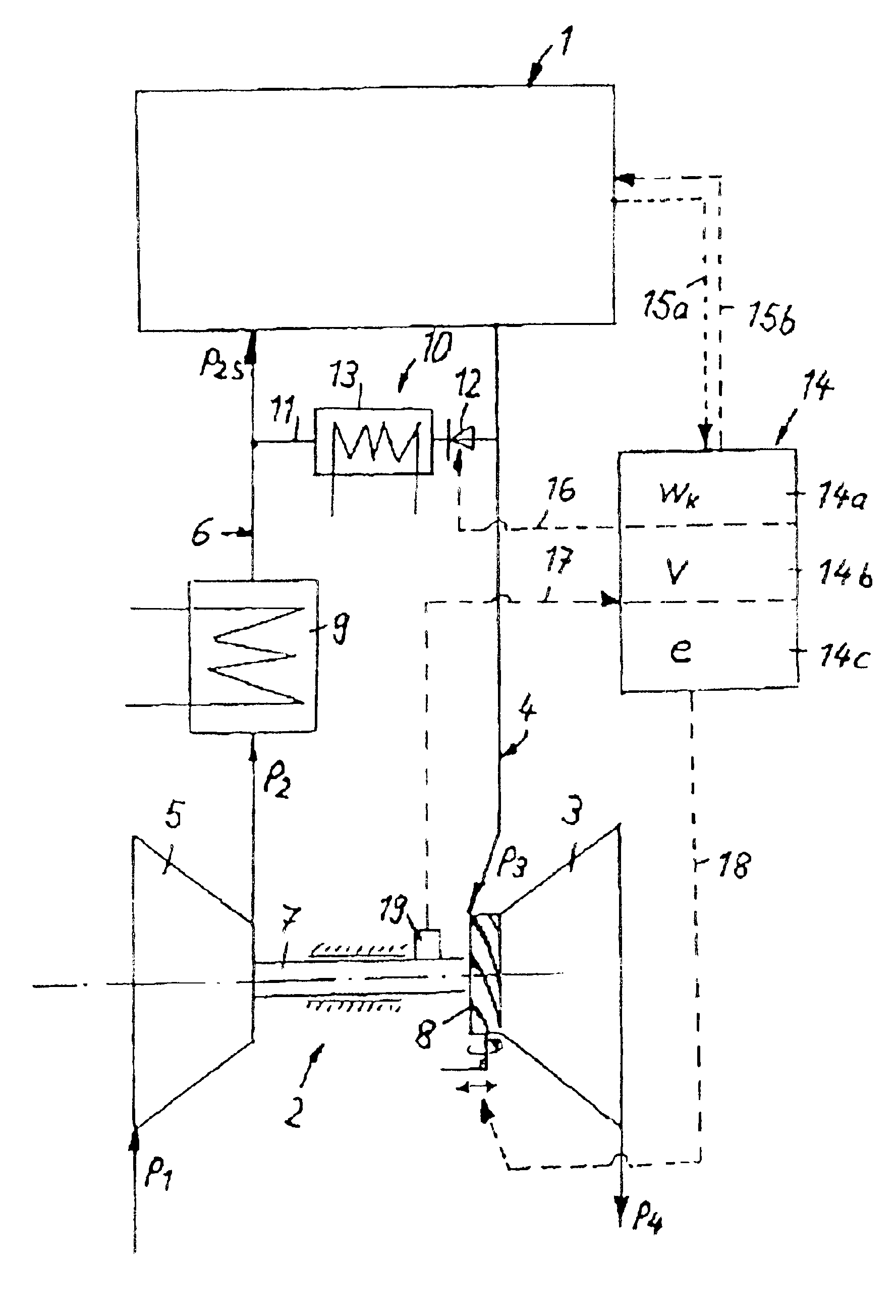
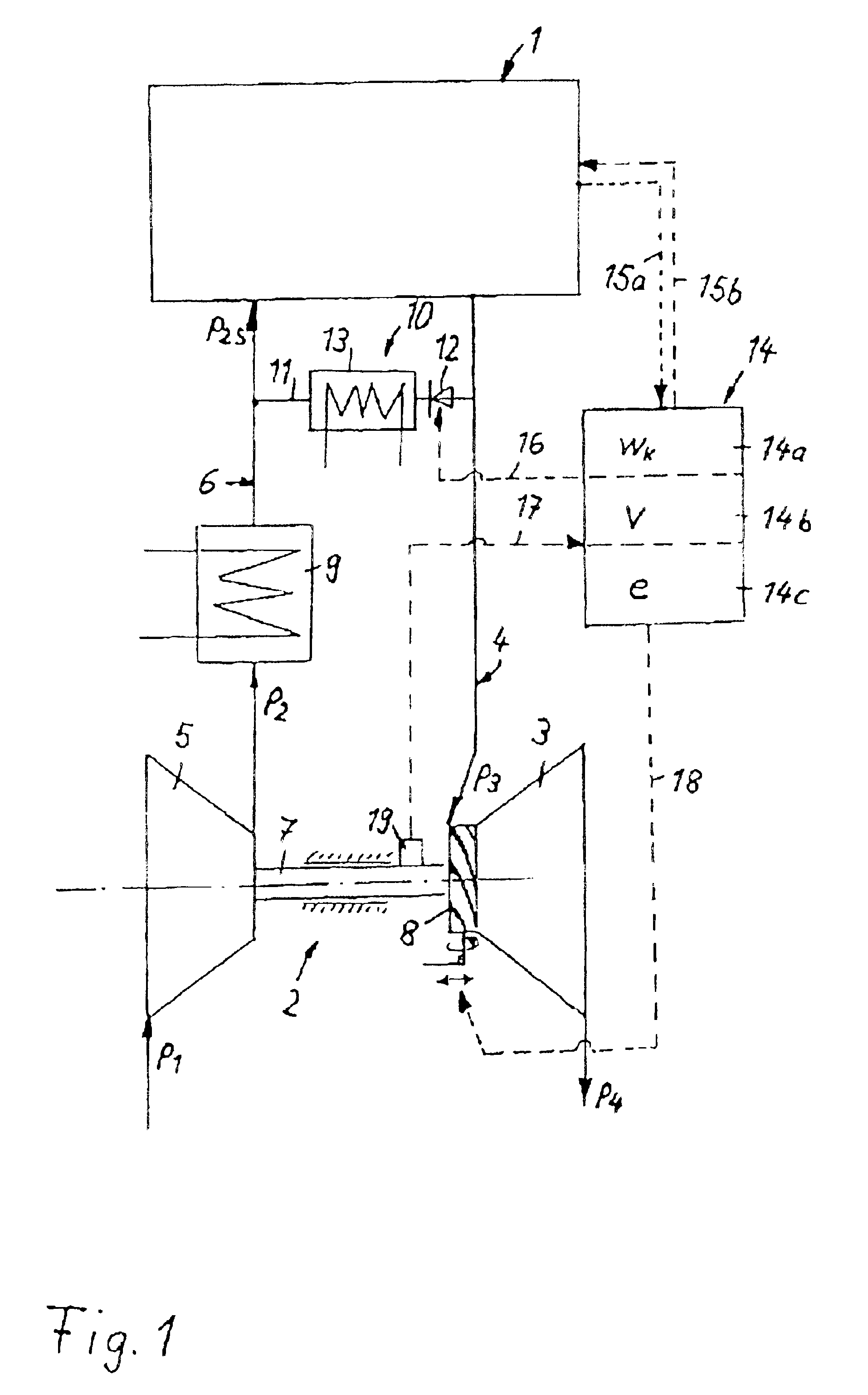
The internal combustion engine 1 illustrated in FIG. 1—a diesel engine or a spark ignition engine—is assigned, as an additional unit, an exhaust turbocharger 2 with an exhaust turbine 3 in the exhaust section 4 and a compressor 5 in the induction tract 6, the compressor 5 being driven via a shaft 7 of the exhaust turbine 3. The compressor 5 sucks in ambient air at atmospheric pressure p1 and compresses it to the elevated pressure p2. In the induction tract 6 downstream of the compressor 5 there is a charge air cooler 9, in which the compressed air is cooled. After it has passed through the charge air cooler 9, the charge air is fed under the charge pressure p2s to the cylinder intakes of the internal combustion engine 1.

On the exhaust side, the exhaust turbine 3 is driven by the exhaust gases in the exhaust section 4, which are under the exhaust gas backpressure p3. After they have flowed through the exhaust turbine, the exhaust gases adopt the expanded pressure p4 and, as they pass...


PUM


Abstract

In a method for diagnosis of an exhaust turbocharger for an internal combustion engine, at least one value which characterizes the load on the exhaust turbocharger is determined and compared with a reference value, an event signal being generated in the event of the reference value being exceeded. A wear characteristic number which characterizes the alternating load on the exhaust turbocharger is formed by addition of load signals, in each case one change signal being generated whenever the charger speed of the exhaust turbocharger exceeds a maximum.

Description

CROSS-REFERENCE TO RELATED APPLICATIONSThe present application claims priority to Application No. 101 40 121.3, filed in the Federal Republic of Germany on Aug. 16, 2001, which is expressly incorporated herein in its entirety by reference thereto.FIELD OF THE INVENTIONThe present invention relates to a method and an appliance for diagnosis of an exhaust turbocharger for an internal combustion engine.BACKGROUND INFORMATIONTurbochargers in internal combustion engines are subject to high centrifugal forces due to high rotational speeds. These forces lead to correspondingly high loads on the material of the turbine wheel and of the compressor wheel of the exhaust turbocharger. These loads can lead to damage to the rotating components and therefore to failure of the exhaust turbocharger. To determine that the load limit has nearly been reached and to avoid damage, it is provided, in accordance with European Published Patent Application No. 0 491 275, for the ratio of boost pressure to in...

Claims


Application Information

Patent Timeline
IPC IPC(8): F02B39/16F02B39/00F02B37/24F02B37/12
CPCF02B39/16F02B37/24
Inventor SCHMID, WOLFRAMWEDLER, HARALD
Owner DAIMLER AG
Why Eureka
Try Eureka