Portable dynamic positioning system with self-contained electric thrusters

a dynamic positioning and self-contained technology, applied in the direction of steering initiation, instruments, vessel construction, etc., can solve the problems of anchor damage to coral reefs, anchor mooring system, anchor breakage of existing pipe lines and cables,

Active Publication Date: 2005-02-01
BEKKER JOANNES RAYMOND MARI
View PDF8 Cites 149 Cited by
  • Summary
  • Abstract
  • Description
  • Claims
  • Application Information

AI Technical Summary

Benefits of technology

Each thruster includes a skid removably mounted to the deck or side of the vessel. The skid accommodates the upper thruster housing, which is moveably connected to the skid. The upper thruster housing contains the azimuthing drive and feedback assembly, consisting of steering gear with electric slewing drive and electrical steering angle feedback sensors. The upper thruster housing also contains a multi-conductor slip ring assembly, providing uninterrupted electrical power to the propeller motor while allowing free azimuthing of the thruster.

Problems solved by technology

As oil and gas exploration is extending farther and farther offshore from land, more and more of these projects are taking place in water depth sufficiently great that it is impractical, sometimes impossible to use anchor mooring systems.
Even in some shallow water areas, the use of anchor mooring systems may be prohibited, for instance, due to the presence of coral reefs or in locations where there already are multiple pipe lines and cables on the ocean floor and the use of anchors could damage the coral reefs or break existing pipe lines and cables.

Method used


Image

  • Portable dynamic positioning system with self-contained electric thrusters
  • Portable dynamic positioning system with self-contained electric thrusters
  • Portable dynamic positioning system with self-contained electric thrusters

Examples


Embodiment Construction

Before explaining the present apparatus in detail, it is to be understood that the apparatus is not limited to the particular embodiments and that it can be practiced or carried out in various ways.

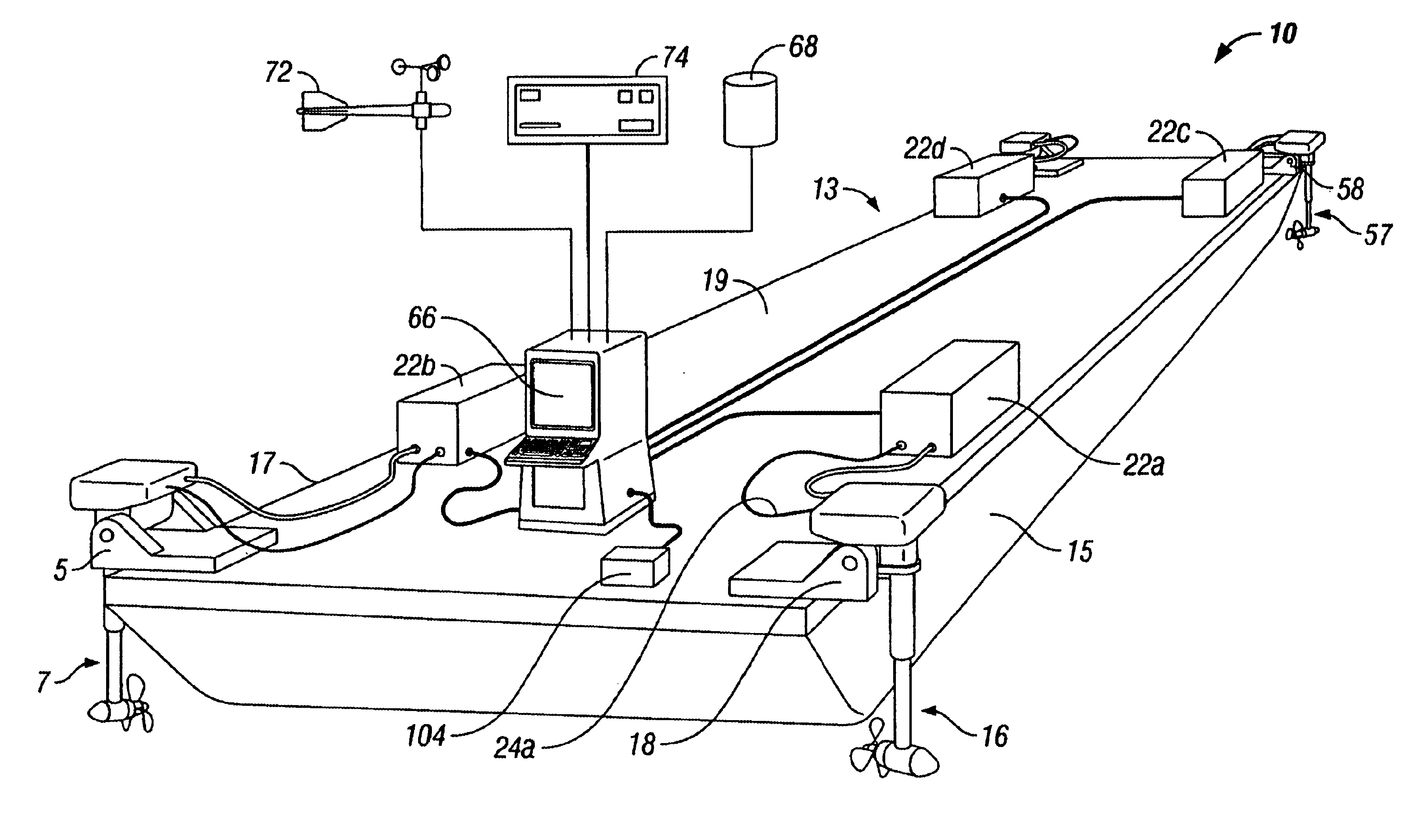
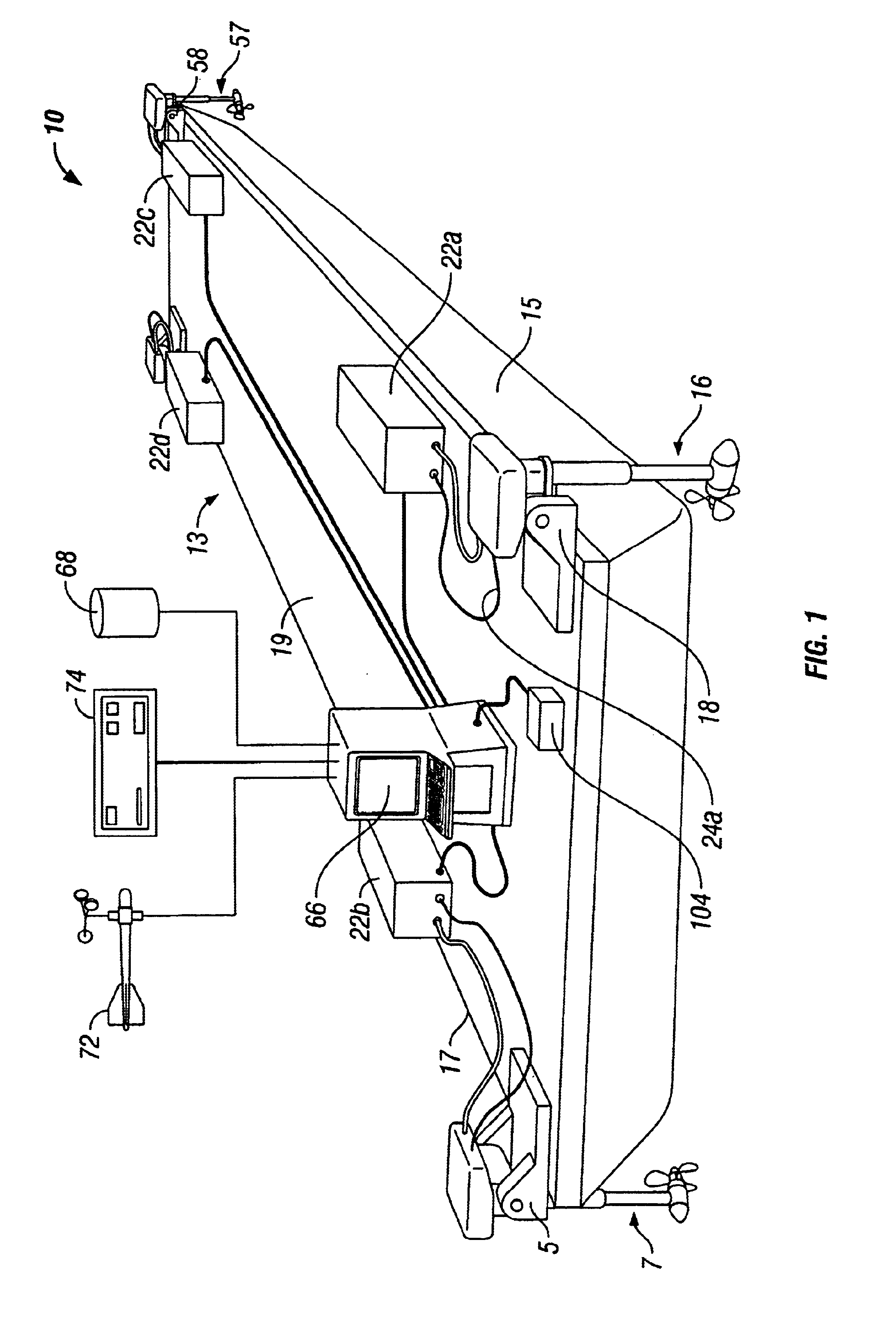
The system as shown in FIG. 1 is an integrated and self-contained electric thruster system (10) for dynamic positioning of any waterborne vessel (13). In this FIG. 1, the vessel is shown to be a barge. The vessel preferably has a hull with at least two sides. For the mono-hull barge shown in FIG. 1, the port side is (15) and the starboard side is (17). A deck (19) connects the sides.

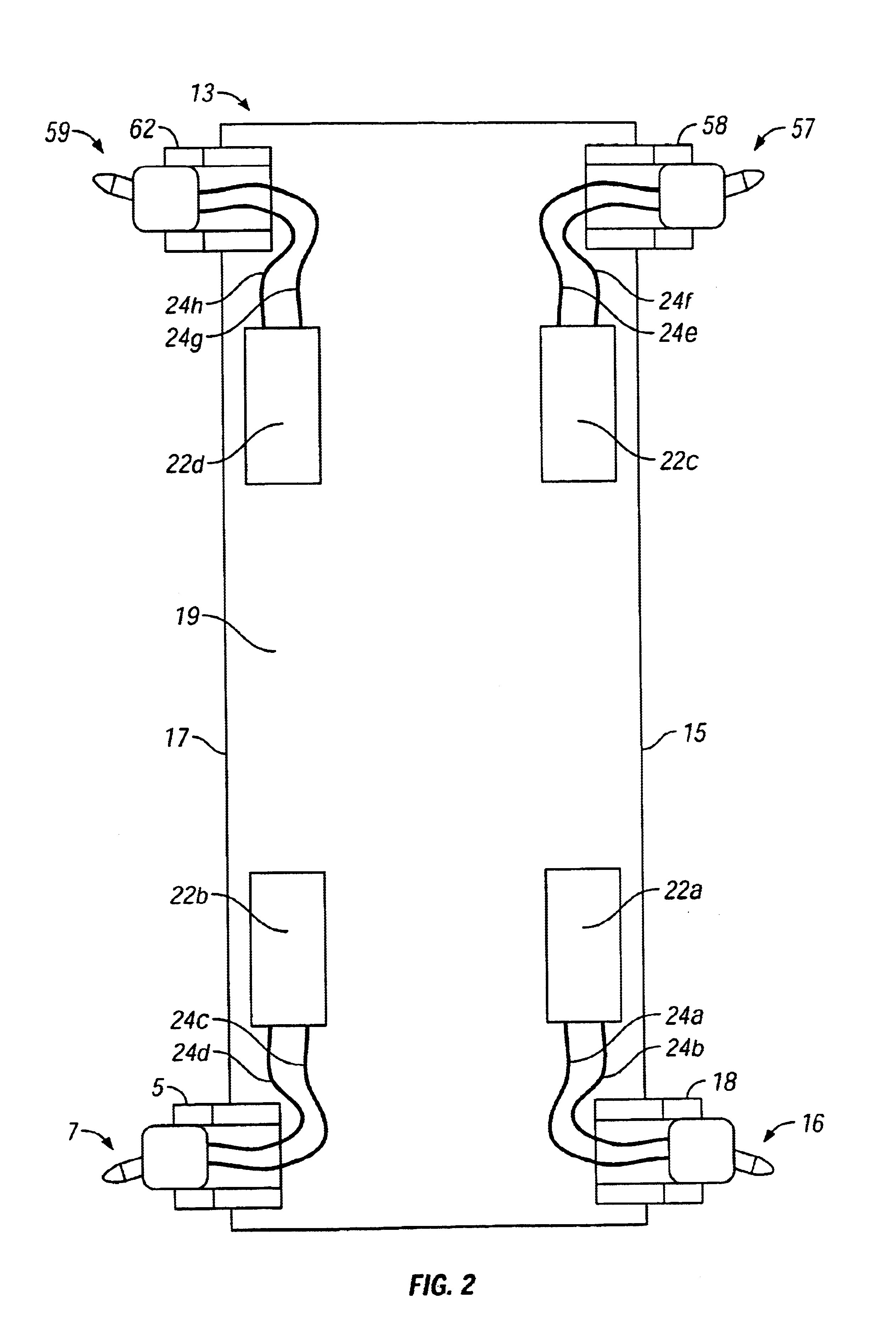
The thruster system is configured from at least two azimuthing thrusters (7) and (16). Each azimuthing thruster is removably mounted to the hull of the vessel.

The azimuthing thruster is mounted to the hull with a skid. FIG. 1 shows that azimuthing thruster (7) is removably mounted to the deck (19) with a skid (5). Similarly, azimuthing thruster (16) is removably mounted to the deck (19) with skid (18).

At least...


PUM


Abstract

The system is an integrated and self contained electric thruster system integral with a dynamic positioning control system for dynamic positioning of any waterborne vessel having a hull with at least two sides and a deck connecting the sides, at least two azimuthing thrusters, each removably mounted to the vessel, at least two self-contained electric power units removably secured to the deck, one for each thruster, at least one dynamic positioning computer connected to each of the self contained electric power units, at least one motion reference sensor connected to the dynamic positioning computer to correct reference position signals for motion of the vessel, at least one heading sensor, and at least one sensor that is either a position reference sensor connected to the dynamic positioning computer, environmental sensors connected to the dynamic positioning computer, or a combination thereof.

Description

FIELDThe embodiments pertain to an integrated positioning and maneuvering system mounted on a vessel hull. More particularly, the embodiments pertain to the portability and installation methods that provide deployed and elevated (service or maintenance) positions of the thrusters and their self-contained power systems and controls relative to a vessel hull.BACKGROUNDMany different types of work performed at sea or on the ocean floor require vessels, barges or other floating platforms that need to hold station in open sea or accurately follow pre-determined tracks relative to the ocean floor. Projects requiring such vessels include offshore drilling, subsea pipelay and cable lay, subsea construction, salvage and recovery, oceanographic research, etc.The vessels, barges and floating structures used for such projects are often equipped with multiple anchors and winches, commonly referred to as anchor mooring systems. They require support of anchor handling vessels to position the ancho...

Claims


Application Information

Patent Timeline
Patent Type & Authority Patents(United States)
IPC IPC(8): B63H20/00B63H25/42B63H25/04B63H25/00B63H23/00B63H23/24
CPCB63H20/00B63H21/17B63H25/42B63H25/04B63H23/24B63J2099/006B63H2020/003B63H2025/045B63B79/15
Inventor BEKKER, JOANNES RAYMOND MARI
Owner BEKKER JOANNES RAYMOND MARI
Why Eureka
Try Eureka