
Vapor vent valve

Inactive Publication Date: 2005-02-01
TI GRP AUTOMOTIVE SYST LLC
View PDF15 Cites 31 Cited by
  • Summary
  • Abstract
  • Description
  • Claims
  • Application Information

AI Technical Summary

Benefits of technology

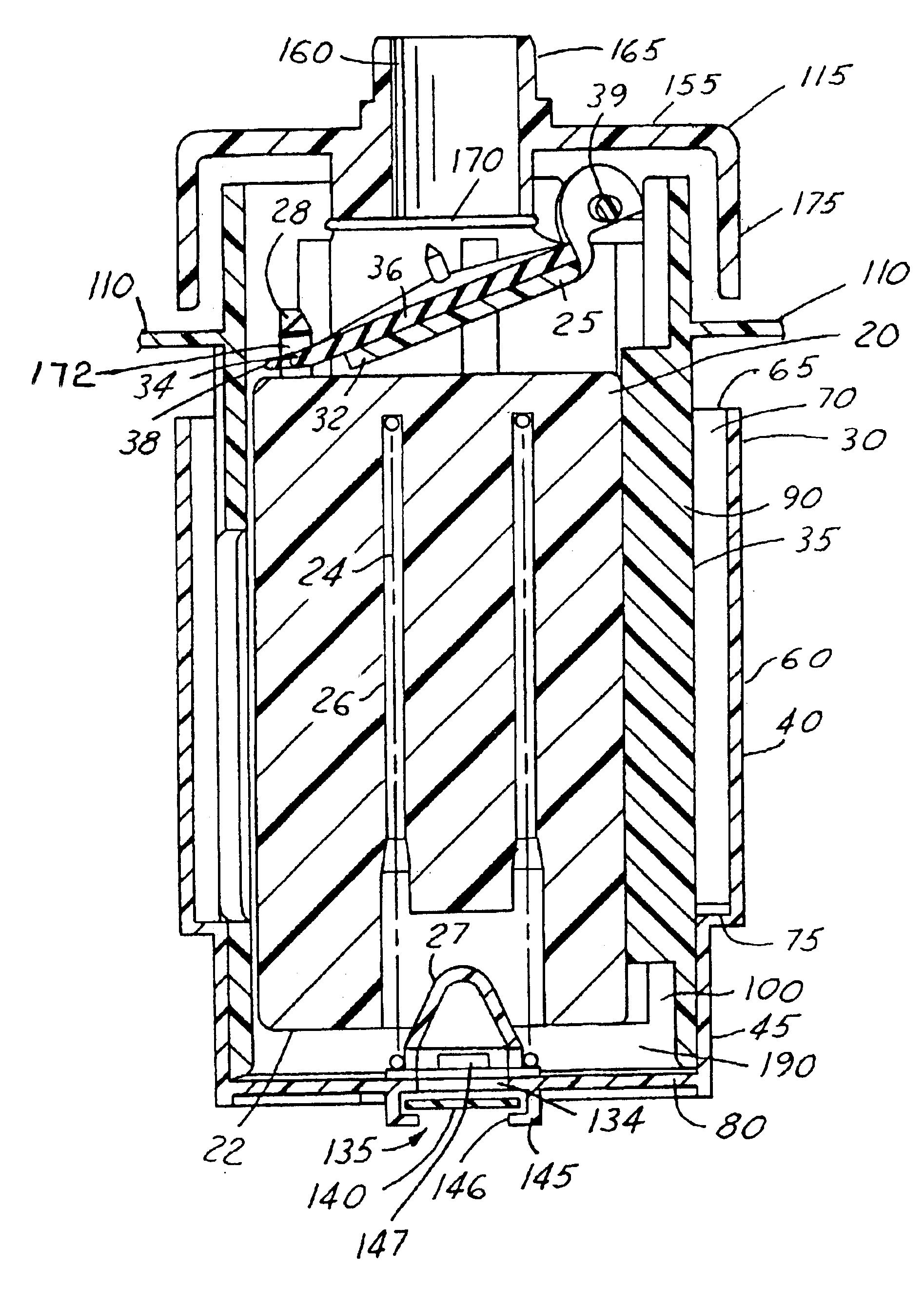
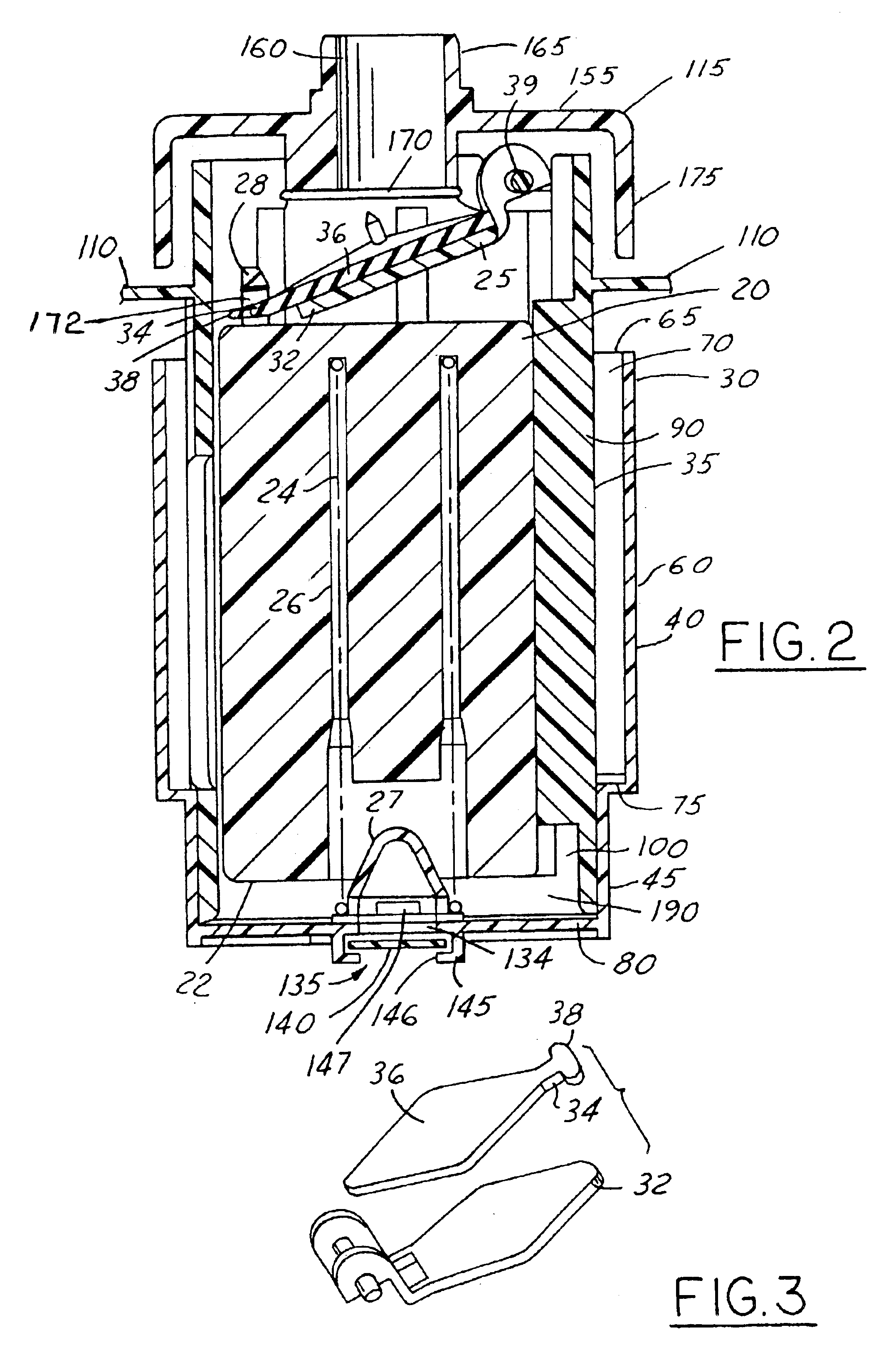
For a fuel tank, a vapor vent valve assembly with a vapor outlet that connects an interior of the fuel tank with an exterior of the fuel tank. The vent valve also includes a fill cup that has an opening at one end and a sidewall that extends from the open end. A shell defines an interior space and is disposed partially in the fill cup. The shell includes a sidewall that has an opening and an upper edge. A flow passage is defined between the fill cup's sidewall and the shell sidewall to allow fuel which flows into the opening of the fill cup to enter the interior space through the opening in the sidewall of the shell. A float is received in the interior space and is responsive to the level of liquid fuel in the interior space. A closure pivotally carried by the shell is movable to a closed position to prevent fluid flow through the vapor outlet. The closure is also movable to an open position which allows fuel vapor to exit the fuel tank. The closure includes a carrier plate that has an elastomeric layer attached to the carrier plate. The elastomeric layer includes a portion that is attached to the float for actuating the closure to the open and closed positions.
Objects, features and advantages of this invention include a vapor vent valve which complies with governmental environmental regulations, has a high vapor flow rate or capacity, during refueling provides timely actuation of an automatic shut-off of a fuel dispensing nozzle as the tank reaches its desired filled fuel level, prevents fuel spit-back during filling, enables multiple shut-offs of the fuel filler nozzle during refueling, prevents the canister from receiving liquid fuel even under fuel splashing and sloshing conditions, closes in a vehicle roll-over condition, maintains a fuel tank gas vapor dome under attempted overfilling conditions, is sensitive and responsive to changes in fuel level and is rugged, durable, reliable, and of relatively simple design, economical manufacture and assembly, and has a long useful life in service.

Problems solved by technology

Governmental regulations also mandate that a vapor control valve remain closed during a vehicle rollover, such that fuel does not escape from the fuel tank and pose a hazard.

Method used


Image

  • Vapor vent valve
  • Vapor vent valve
  • Vapor vent valve

Examples


Embodiment Construction

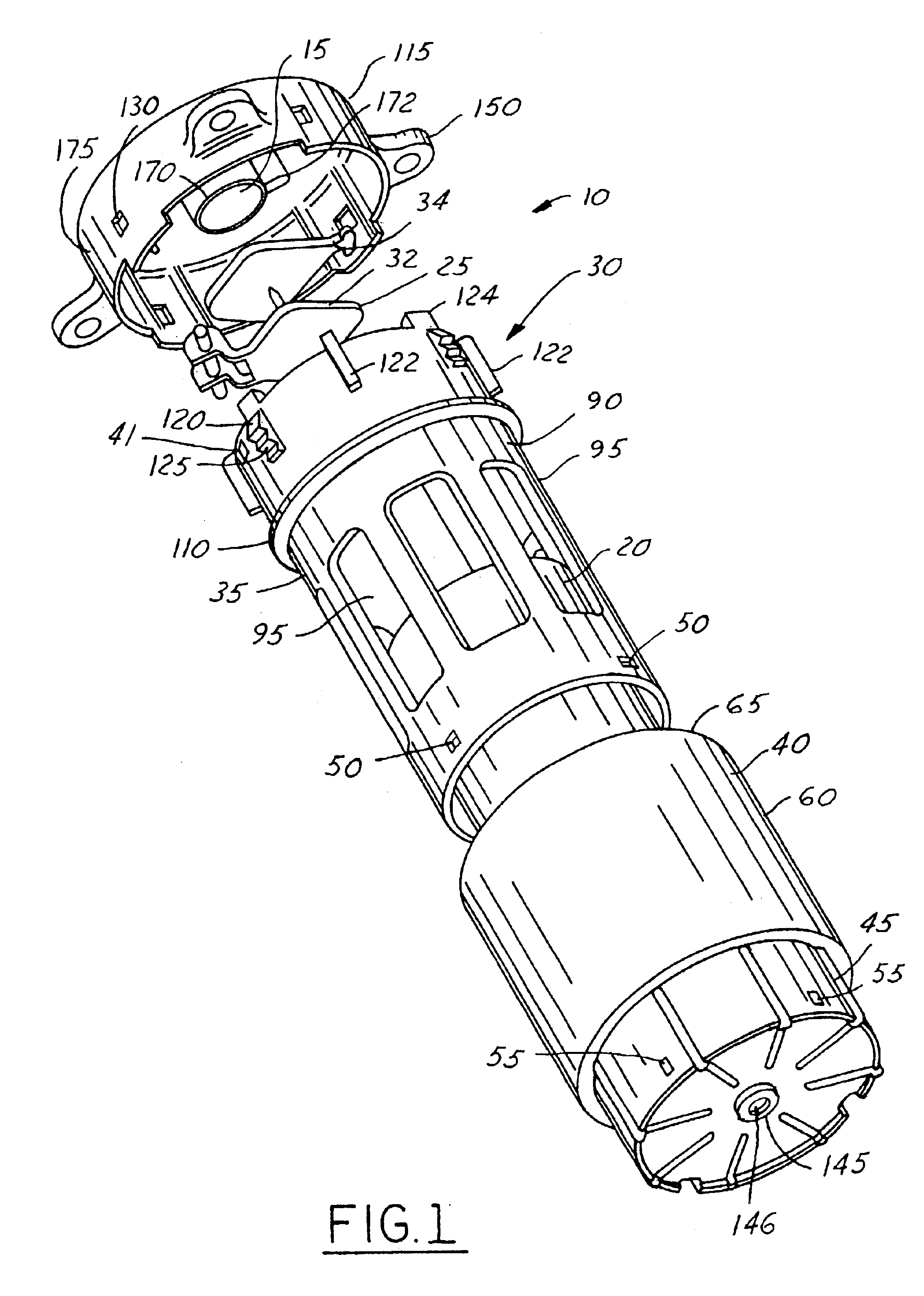
FIG. 1 illustrates a fuel vapor vent valve 10 embodying this invention constructed to be mounted on a fuel tank in communication with the interior of the fuel tank and selectively permits fuel vapor to flow out of the fuel tank through a vapor outlet 15 of the vent valve 10. The vapor vent valve 10, as shown, is a stand-alone component which may be separately mounted on the fuel tank, or alternatively may be incorporated as a portion of a fuel pump module that is mounted on the fuel tank. The vent valve 10 has a float 20 which actuates a closure 25 that is engageable with the vapor outlet 15 to substantially close the vapor outlet 15.

During refueling, the shutoff of the vapor outlet 15 controls the filling of the fuel tank. When the closure 25 engages the vapor outlet 15, vapor flow out of the fuel tank is restricted and pressure within the tank increases. This causes fuel to back up within a fill pipe of the fuel tank, thereby closing off a control port of a refueling nozzle as is ...


PUM


Abstract

A vapor vent valve for a fuel tank that includes a vapor outlet that connects an interior of the fuel tank with an exterior of the fuel tank. The vent valve also includes a fill cup that has an opening at one end and a sidewall that extends from the open end. A shell defines an interior space and is disposed partially in the fill cup. The shell includes a sidewall that has an opening and an upper edge. A flow passage is defined between the fill cup's sidewall and the shell sidewall to allow fluid which flows into the opening of the fill cup to enter the interior space through the opening in the sidewall of the shell. A float is received in the interior space and is responsive to the level of liquid fuel in the interior space. A closure pivotally carried by the shell is movable to a closed position to prevent fluid flow through the vapor outlet. The closure is also movable to an open position which allows fuel vapor to exit the fuel tank. The closure includes a carrier plate that has an elastomeric layer attached to the carrier plate. The elastomeric layer includes a portion that is attached to the float for actuating the closure to the open and closed positions.

Description

FIELD OF THE INVENTIONThis invention relates to a vapor vent valve for a vehicle fuel tank, and more particularly to a vapor vent valve having a closure that includes an elastomeric layer attached to a single float.BACKGROUND OF THE INVENTIONEnvironmental concerns and governmental regulations require reduced emissions of volatile hydrocarbon fuel vapors into the atmosphere. One source of hydrocarbon fuel vapors is fuel tanks of vehicles using gasoline or other high volatility hydrocarbon fuels. Fuel vapor can escape to the atmosphere during filling of fuel tanks and even after the tanks are filled. The use of vapor recovery systems to remove excess fuel vapor from the fuel tank is one solution that is commonly used to abate the problem. Such systems may include, a canister having activated charcoal therein which receives fuel vapors through a valve assembly mounted in the top of the fuel tank and communicates with the intake manifold of the vehicle engine for withdrawing fuel vapor ...

Claims


Application Information

Patent Timeline
IPC IPC(8): F16K24/04F16K24/00
CPCF16K24/044Y10T137/0874Y10T137/3099
Inventor JOHANSEN, MARK R.
Owner TI GRP AUTOMOTIVE SYST LLC
Learn More