Radiation reflector

Inactive Publication Date: 2005-02-01
TAGIROV DJALALUTDIN TAJUTDINOVICH
View PDF8 Cites 12 Cited by
  • Summary
  • Abstract
  • Description
  • Claims
  • Application Information

AI Technical Summary

Benefits of technology

The task of the present invention consists of expanding the functional capabilities of the reflector by providing spherical reflecting surfaces of small radius of curvature and rectangular radiation reflectors. The

Problems solved by technology

Among reasons that prevent achievement of the desired technical result when using this device is the fact that a mirror sheet of the reflector is released under the influence of centrifugal force arising by its rotation.
A large-sized gyrating reflector provokes the force of inertia, whic

Method used


Image

  • Radiation reflector
  • Radiation reflector
  • Radiation reflector

Examples


Embodiment Construction

As described herein, the present invention includes designs of radiation reflectors as shown in FIGS. 1a-13f.

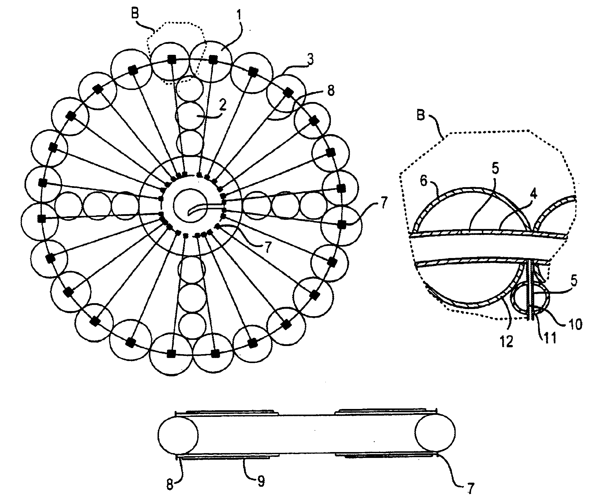
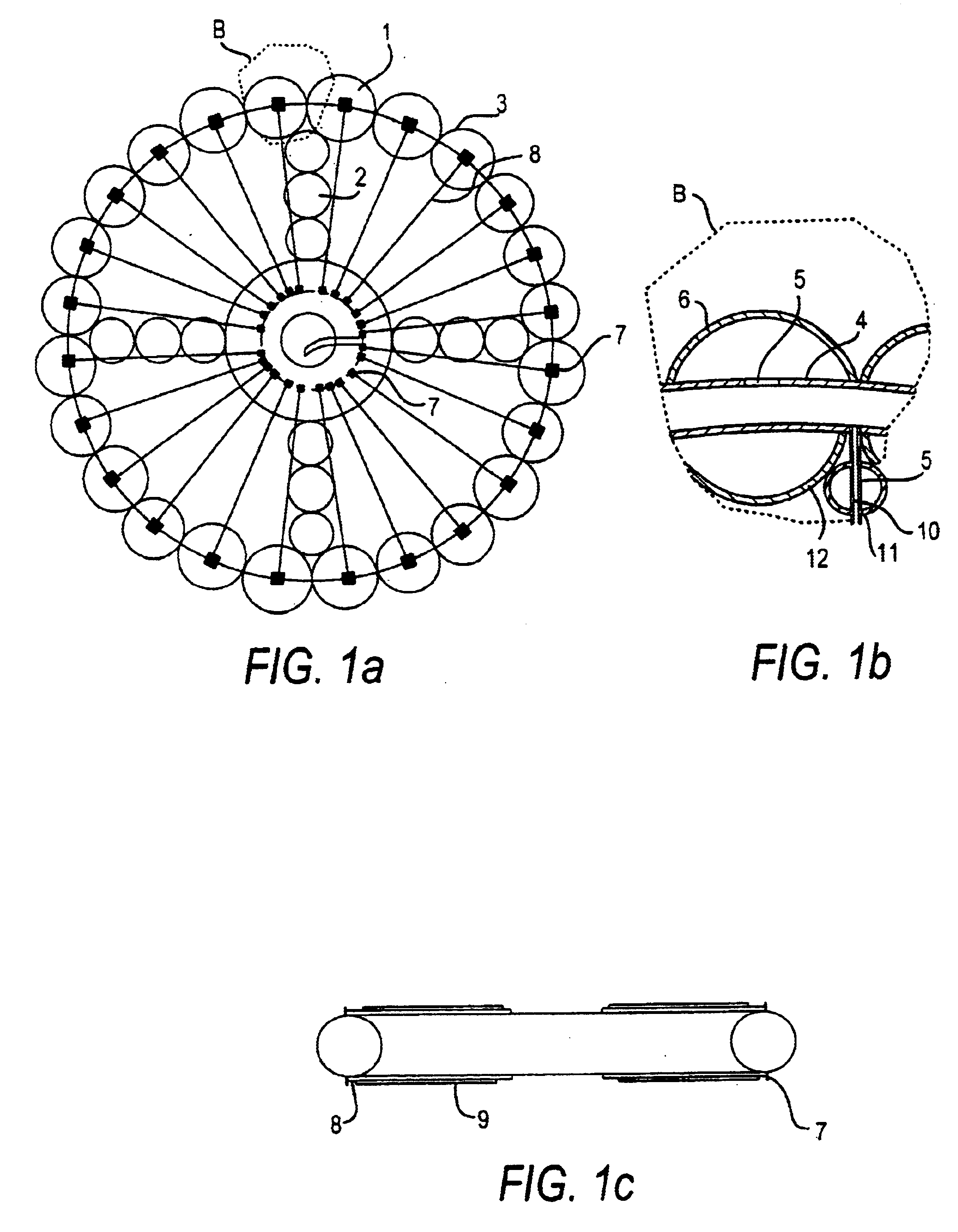
FIGS. 1a-1cshow the design of a radiation reflector having the following components:1—external pneumatic chamber;2—radial supports;3—internal pneumatic chamber;4—concentric tube;5—apertures;6—globular pneumatic cells;7—fastening eyelets;8—taut bands or threads;9—mirror sheet;10—radial tube;11—radial pneumatic cells; and12—joint of radial and concentric tubes.

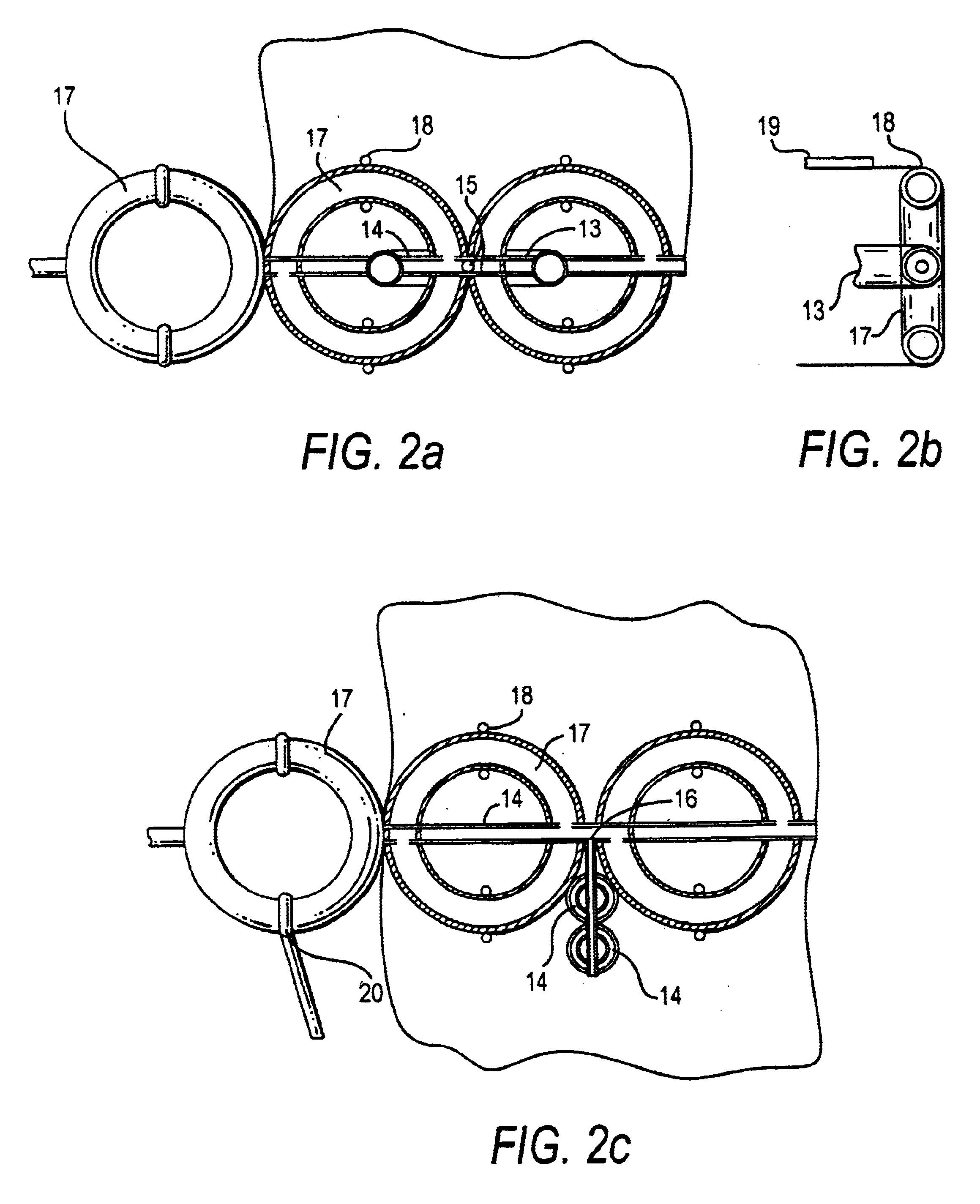
FIGS. 2a-2c show the design of a radiation reflector, which is unfolded with the help of toroidal pneumatic chambers, having the following components:13—radial pneumatic chambers;14—flexible tube;15—apertures;16—of concentric and radial tubes;17—concentric external pneumatic chamber;18—taut bands or threads;19—mirror sheet; and20—connection for traction with the concentric external pneumatic chamber 17.

FIGS. 3a-3b show the design of a reflector, in which toroidal pneumatic chambers are connected to make a chain, having t...


PUM


Abstract

A radiation reflector may be used in space telecommunications, having spherical reflecting surfaces and/or rectangular reflecting surfaces which may be folded, as required. The radiation reflector has an arrangement of reflecting surfaces on foldable frames which may be in the form of interacting balls or rings mounted on pneumatic tubes or ropes.

Description

BACKGROUND OF THE INVENTION1. Field of the InventionThe invention concerns space engineering, namely, space communication engineering.2. Description of the Related ArtThere are well-known large-sized film reflectors of light, which could be used for space radio-telephone communications and night-time illumination of ground objects from space, as described in Project “Znamya”, Rocket Space Complex “Energia”.Among reasons that prevent achievement of the desired technical result when using this device is the fact that a mirror sheet of the reflector is released under the influence of centrifugal force arising by its rotation.A large-sized gyrating reflector provokes the force of inertia, which hinders the control of the device and the pointing of it at the object to be illuminated.There are also reflectors of electromagnetic radiation, such as light, with the nearest to the aforementioned device in purpose and combination of essential attributes being described in S. D. Amirov and A. S...

Claims


Application Information

Patent Timeline
IPC IPC(8): B64G1/10B64G1/66B64G1/00B64G1/22G02B5/10G02B7/182H01Q1/28H01Q15/14H01Q1/27H01Q15/16H01Q1/08G02B5/12G02B7/183
CPCB64G1/1007B64G1/222B64G1/66H01Q15/163G02B7/183H01Q1/081H01Q1/288H01Q15/161G02B5/10B64G2001/224B64G1/2227
Inventor TAGIROV, DJALALUTDIN TAJUTDINOVICH
Owner TAGIROV DJALALUTDIN TAJUTDINOVICH
Why Eureka
Try Eureka