Magnetic conditoning of fluids and gases and apparatus therefor

a technology applied in the field of magnetic conditoning of fluids and gases and apparatus therefor, can solve the problems of sacrificing the initial, beneficial effects of incremental conditioning, affecting the efficiency of incremental conditioning, and the duration between the magnetic conditioning process, so as to improve the specific magnetic field, reduce the propensity for conceptual flux lines, and improve the effect of flux density

Inactive Publication Date: 2005-02-01
SACS STEVEN
View PDF4 Cites 22 Cited by
  • Summary
  • Abstract
  • Description
  • Claims
  • Application Information

AI Technical Summary

Benefits of technology

A specific advantage of the invention is the application of the magnetic technology in incrementally higher, non-uniform levels to effect a sequentially staged and consistently greater degree of spinflip.
is the application of the magnetic technology in incrementally higher, non-uniform levels to effect a sequentially staged and consistently greater degree of spinflip.
An important advantage of the invention is the application of advanced insulative shielding to both enhance and encapsulate the specific magnetic field of the invention. Said shielding functions; firstly, to concentrate the effectual area of the magnetic field on the substance's flow path by reducing the propensity of conceptual flux lines to occupy space above and / or aside each magnet. Secondly, it protects the magnetic field of the invention from outside influences and also protects said outside influences from the magnetic field provided by the invention.
Other advantages of this invention will be apparent from consideration of the following specification.
In accordance with certain of its aspects this invention relates to an apparatus for magnetic conditioning of fluid and gas substances flowing through a conduit, said apparatus comprising one to eight two-part paired modules firmly mounted on the exterior surface of said conduit for fluids and gases, each part of each module being substantially parallel to the other part of the module, there being present a magnet in each part of each module in direct contact to said conduit, wherein one of the magnets in each part of each module has a higher flux density than the magnet in the paired parallel part and the polarities and alignment of each of the magnets is such that there is created a mono-directional magnetic field normal to the direction of flow of said substances in said conduit and wherein the side of one of said magnets of said module facing said conduit is opposite in polarity to the polarity of the magnet opposite to it.
Preferably the magnets are of high flux density and are heat stabilized anisotropic. The specific levels of magnetic strength of these high flux magnets are not critical. For instance, the magnet in one part of the module may have a flux density strength of about 2,200 Gauss or less to about 10,200 Gauss or more and the magnet opposite to it may have a strength of about 3,850 Gauss or less to about 11,000 Gauss or more, so long as the strengths are different, for example by at least about 800 Gauss.

Problems solved by technology

However, his implied use of such a design in a fuel tank raises concerns about duration between the magnetic conditioning process and the purported use of the fuel.
Here the patentee suggests that the use of an exterior clamp member made of a metallic material will “provide a continuous and uninterrupted metallic flux flow path.” The patent represents that the re-directing of the external flux flow path is meant to increase the flux density and therefore provide magnetic devices with the ability to attain greater efficiency in the treatment of substances; however, such a magnetic flow path reduces the smooth transition of a flowing substance into the realm of the magnetic field, thereby sacrificing the initial, beneficial effects of incremental conditioning.

Method used


Image

  • Magnetic conditoning of fluids and gases and apparatus therefor
  • Magnetic conditoning of fluids and gases and apparatus therefor
  • Magnetic conditoning of fluids and gases and apparatus therefor

Examples


Embodiment Construction

Numbers applied to aspects of one Figure that repeat in other Figures are unchanged with respect to the features described.

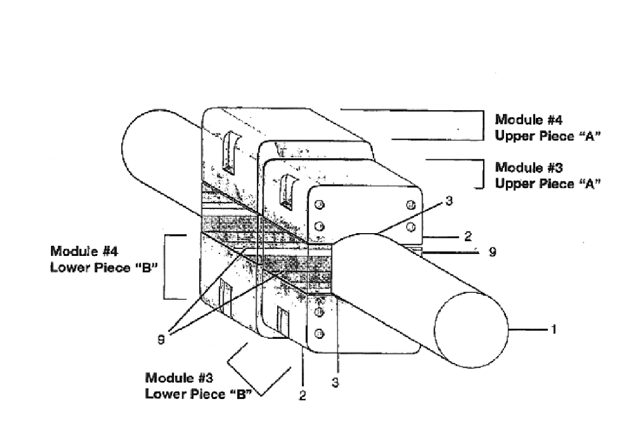
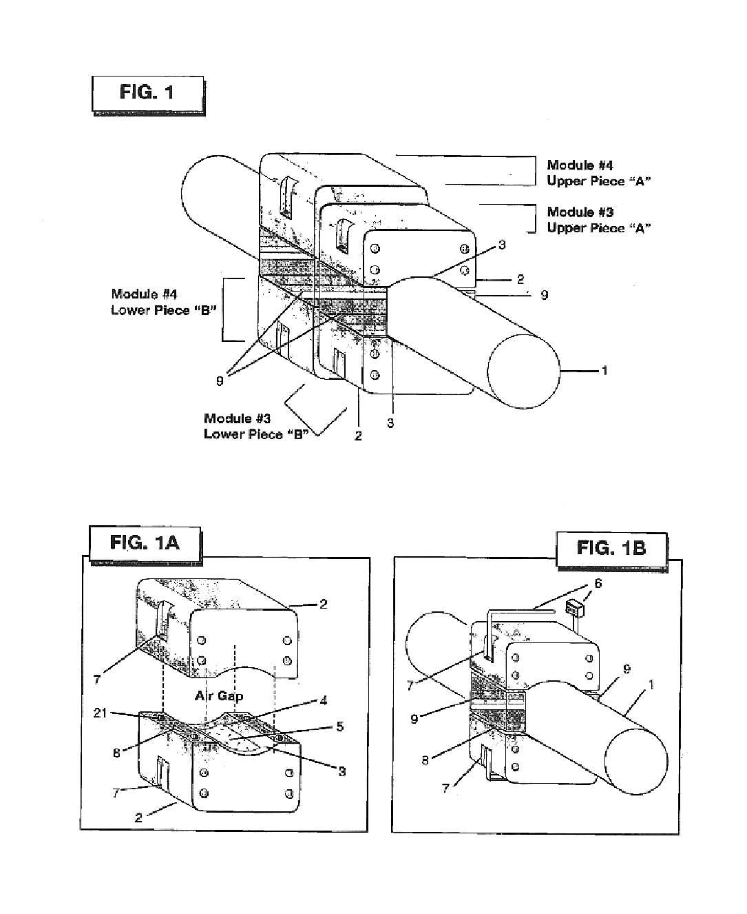
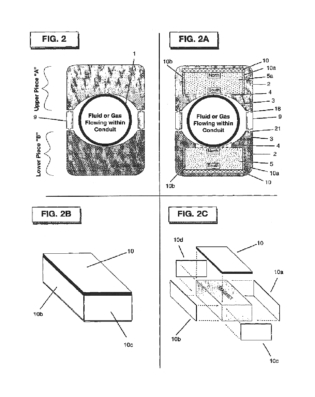
The invention consists of a minimum of one, 2-piece module (with an upper piece (A) and a lower piece (B), as shown in FIG. 1). Although the total system could be comprised of up to eight modules, as few as one module may be applied effectively. Modules are configured about a conduit 1 or other containment vessel in which a fluid or gas is flowing. Each piece (upper A and lower B) of a modular pair consists of an exterior housing 2 constructed of a non-magnetic material such as, but not limited to plastic. This housing is typically of rectangular proportions, with rounded edges along the top and side faces. Magnets 5 and 5a that are contained within the housing are also of similar shape (magnet 5 is shown in FIG. 1A). The magnets of a module are aligned with respect to polarity to create a mono-directional magnetic field normal to the direction of flow of the su...


PUM

PropertyMeasurementUnit
temperatureaaaaaaaaaa
distanceaaaaaaaaaa
distanceaaaaaaaaaa

Abstract

Magnetic conditioning of fluids and gases flowing through a conduit or other containment vessel to achieve essentially uniform characteristics of said fluids and gases for the purposes of improved operation efficiency and performance quality of mechanisms and systems dependent on these liquids and gases. Specifically, the invention pertains to a combined application of advanced techniques including 1) use of magnets, preferably high flux density stabilized anisotropic magnets, 2) non-uniform flux density pairing, 3) magnetic field focused on an air gap using advanced insulative shielding and parallel alignment control, 4) incremental conditioning and 5) modular design.

Description

The application of magnetic conditioning techniques has been used to effect performance of flowing substance based mechanisms or systems. The use of such techniques on the flow of hydrocarbon compound fuels through vehicle fuel lines to create more complete combustion, as well as for flow of domestic and industrial water within pipes to reduce calcium scaling along conduit walls, are two typical examples. The understanding of these applications are well known emanating from early work of scientists such as Faraday, van der Waals and Divac.BACKGROUNDIf left unaffected by external influences, such as temperature change or the introduction of a magnetic field, electrons and their respective atoms within a molecular structure assume a commonly understood state of equilibrium based on bonding characteristics such as the behavior between neighboring valence electrons. However, if an external influence is introduced, the molecular structure reacts to assume a new configuration having the l...

Claims


Application Information

Patent Timeline
Patent Type & Authority Patents(United States)
IPC IPC(8): F02M27/00F02M27/04B01J19/08C02F1/00C02F1/48C02F5/00
CPCF02M27/045C02F1/481C02F2301/024
Inventor SACS, STEVEN
Owner SACS STEVEN
Why Eureka
Try Eureka