Transverse flux linear motor with permanent magnet excitation

Inactive Publication Date: 2005-02-01
KOREA ELECTROTECH RES INST
View PDF7 Cites 24 Cited by
  • Summary
  • Abstract
  • Description
  • Claims
  • Application Information

AI Technical Summary

Benefits of technology

Therefore, the present invention has been made in view of the above described problems, and an object of the invention is to provide a transverse flux linear motor with permanent magnet excitation which has a simple configuration as c

Problems solved by technology

However, such systems have disadvantages of a complex configuration, high manufacturing costs, and high maintenance and repair expenses.
However, these linear motors have disadvantages of low thrust force and low efficiency.
For instance, linear inductio

Method used


Image

  • Transverse flux linear motor with permanent magnet excitation
  • Transverse flux linear motor with permanent magnet excitation
  • Transverse flux linear motor with permanent magnet excitation

Examples


Example

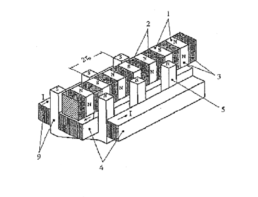
Now, the single-phase configuration of a transverse flux linear motor with permanent magnet excitation according to a preferred embodiment of the present invention will be described in conjunction with FIGS. 1 to 7.

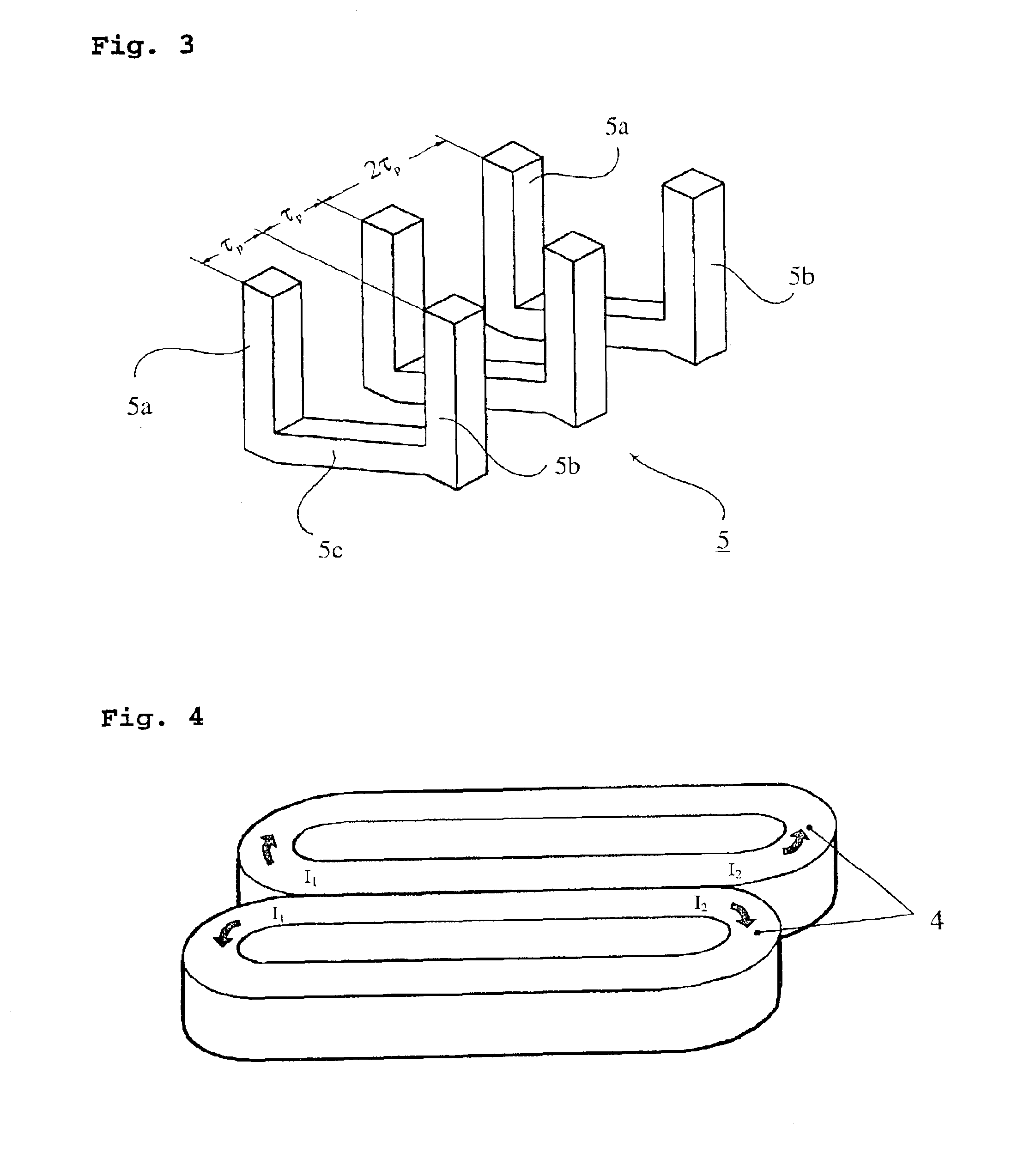
FIG. 1 is a view illustrating the single-phase transverse flux linear motor with permanent magnet excitation. As shown in FIG. 1, the linear motor includes a mover 3 including a plurality of mover cores 1, and a plurality of permanent magnets 2 each arranged between adjacent ones of the mover cores 1. The mover 3 is arranged at the central portion of a stator 9. The stator 9 includes a plurality of stator cores 5, and windings 4 to flow the current.

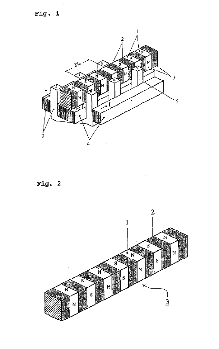
As shown in FIG. 2, the mover 3 has a structure in which each permanent magnet 2 is interposed between adjacent ones of the mover cores 1 to form high magnetic flux in an air gap. The mover cores 1 and permanent magnets 2 have a square or rectangular shape. In FIG. 2, arrows indicate the direction of magnetic flux generated in ...


PUM


Abstract

A transverse flux linear motor with permanent magnet excitation having a stator including stator cores and windings respectively wound around the stator cores and supplied with current, and a mover arranged at a central portion of the stator, the mover including mover cores and permanent magnets. Each of the permanent magnets is arranged between adjacent ones of the mover cores. Each stator core has a pair of column portions spaced apart from each other by a desired distance. The windings are arranged in pairs such that each of the winding pairs has two windings wound around respective column portions of an associated one of the stator cores.

Description

BACKGROUND OF THE INVENTION1. Field of the InventionThe present invention relates to a high-power, high-efficient linear force generating system, and more particularly to a transverse flux linear motor with permanent magnet excitation, which can generate high force while having a relatively simple configuration, thereby achieving a high efficiency.2. Description of the Related ArtGenerally, linear force can be generated using hydraulic or pneumatic pressure, or a power transmission device such as a rotary motor and a ball screw. However, such systems have disadvantages of a complex configuration, high manufacturing costs, and high maintenance and repair expenses.Meanwhile, conventional linear motors have a simple configuration in that they do not require any force transmission device because they directly generate a linear force. However, these linear motors have disadvantages of low thrust force and low efficiency. For instance, linear induction motors for railroad vehicles use a l...

Claims


Application Information

Patent Timeline
IPC IPC(8): H02K41/03H02K41/02
CPCH02K41/03H02K2201/12H02K41/02
Inventor KANG, DO HYUNJEON, JEONG WOO
Owner KOREA ELECTROTECH RES INST
Why Eureka
Try Eureka