Single coil, direct current permanent magnet brushless motor with voltage boost

a permanent magnet, brushless motor technology, applied in the direction of motor/generator/converter stopper, dynamo-electric converter control, magnetic circuit shape/form/construction, etc., can solve the problems of high manufacturing cost of brushless motors, and inability to meet the needs of large-scale equipmen

Inactive Publication Date: 2005-02-01
MCMILLAN ELECTRIC
View PDF19 Cites 37 Cited by
  • Summary
  • Abstract
  • Description
  • Claims
  • Application Information

AI Technical Summary

Benefits of technology

In yet another aspect, a means for providing locked rotor protection can include a Hall sensor configured to turn off the two high-side switches and two low-side switches of the H-bridge for a period of time when the Hall sensor detects a locked rotor condition.
The above summary is not intended to descr

Problems solved by technology

However, the costs associated with the manufacture of brushless motors are usually greater than induction motors.
For example, brushless motors can be more expensive than induction motors because of the control circuitry necessary to drive the brushless motors.
Therefore, until recently, brushless motors have typically been used in larger, expensive equipment such as washing machines and high-efficiency furnaces and in medical and military applications, where cost is less of a factor.
Such a configuration can provide a smooth drive and good starting torque, but is complicated in terms of the number of components and the expense of the components.
Ot

Method used


Image

  • Single coil, direct current permanent magnet brushless motor with voltage boost
  • Single coil, direct current permanent magnet brushless motor with voltage boost
  • Single coil, direct current permanent magnet brushless motor with voltage boost

Examples


Embodiment Construction

This invention relates generally to direct current electric motors. More particularly, this invention relates to a single coil, direct current permanent magnet brushless motor with a voltage boost circuit. While the present invention is not so limited, an appreciation of the various aspects of the invention will be gained through a discussion of the examples provided below.

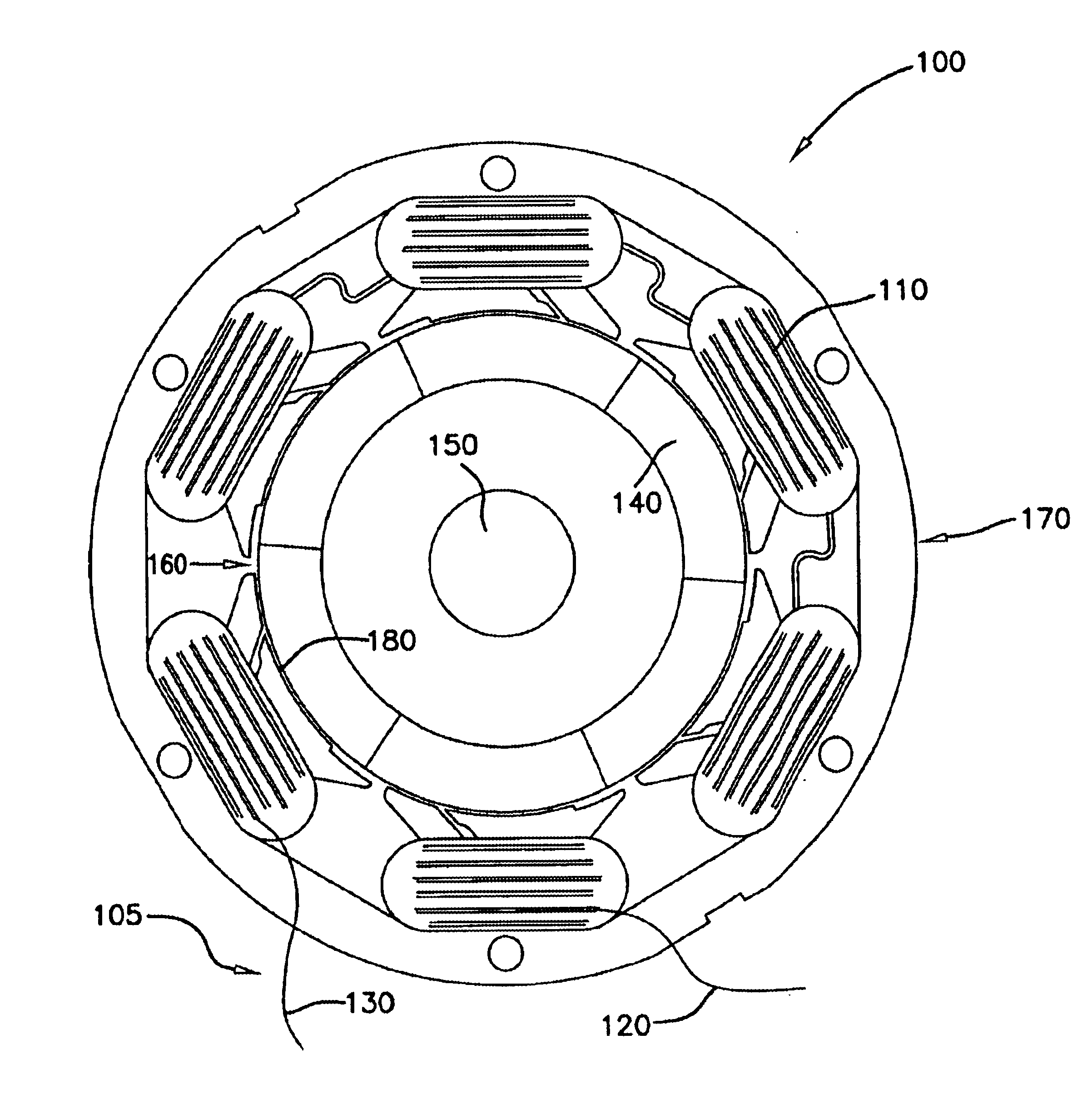
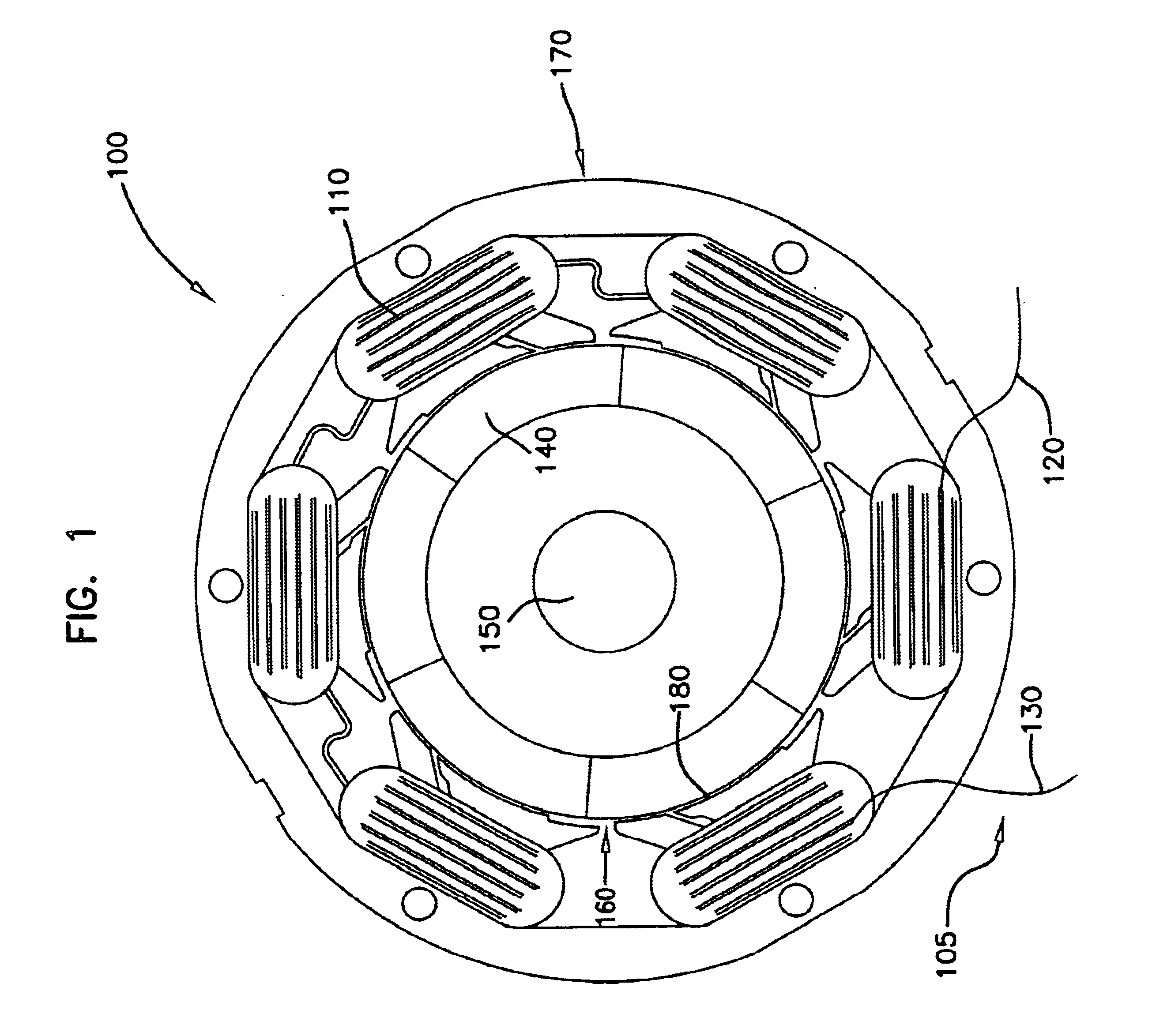
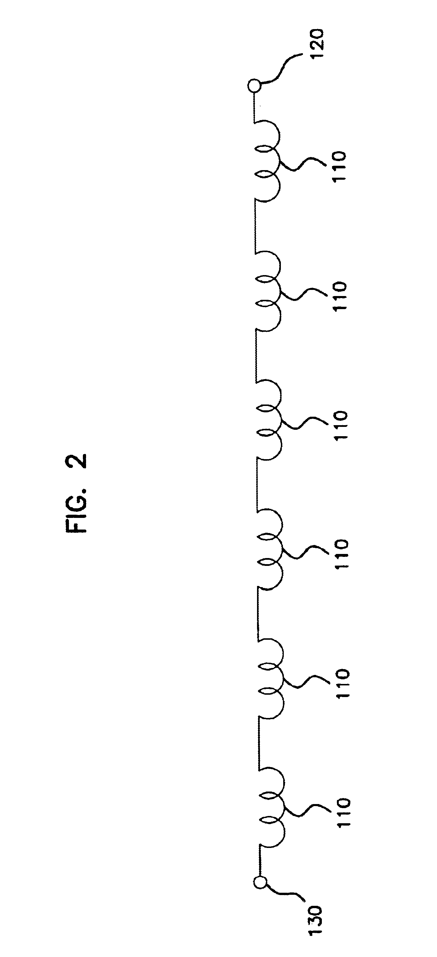
Generally, the present disclosure relates to a single coil, direct current permanent magnet brushless motor including a rotor with alternate-polarity magnets rotatably journaled in the motor and a stator with a like number of stator poles including wound coils connected into a single coil with two ends. Preferably, the motor includes at least four magnets and a like number of stator poles. More preferably, the motor includes six magnets and six stator poles. In addition, the motor includes a commutated H-bridge coupled to the two ends of the single coil to drive the motor.

Referring now to FIG. 1, one embodiment of...


PUM


Abstract

A single coil, direct current permanent magnet brushless motor including a stator including six alternately-wound coils connected into a single coil having first and second ends, the oppositely-wound coils forming stator poles, and six magnets of alternating polarity coupled to a rotor and rotatably journaled in the stator. A sensor, such as a dual output Hall sensor, is used for sensing rotation of the rotor. A drive circuit, such as an H-bridge circuit, is coupled to the first and second ends of the single coil to drive the motor. The H-bridge circuit includes two high-side switches for alternately receiving signals from the Hall sensor, and two low-side switches alternately receiving signals from the Hall sensor. A high-side switching signal can be controlled by an inverted low-side switching signal. A voltage boost circuit is also provided, having capacitors to provide a boosted voltage to alternately turn on the high-side switches of the H-bridge. The capacitors can be charged by an unregulated bus voltage.

Description

TECHNICAL FIELDThis invention relates generally to direct current electric motors. More particularly, this invention relates to a single coil, direct current permanent magnet brushless motor with a voltage boost circuit.BACKGROUNDPermanent magnet brushless electric motors are desirable for efficiency. Brushless motors are typically more efficient and quieter than induction motors because brushless motor designs avoid losses related to the “induction” process. However, the costs associated with the manufacture of brushless motors are usually greater than induction motors. For example, brushless motors can be more expensive than induction motors because of the control circuitry necessary to drive the brushless motors. Therefore, until recently, brushless motors have typically been used in larger, expensive equipment such as washing machines and high-efficiency furnaces and in medical and military applications, where cost is less of a factor.Increased concerns for efficiency and strict...

Claims


Application Information

Patent Timeline
IPC IPC(8): H02P6/08
CPCH02P6/085
Inventor GERFAST, STEN R.
Owner MCMILLAN ELECTRIC
Why Eureka
Try Eureka