Transmit mode coil detuning for MRI systems

a technology of magnetic resonance imaging and transmit mode, applied in the field of radio frequency coils, can solve the problems of large coils, lower signal-to-noise ratio (snr or s/n), and inconvenience of feeding dc current to all diodes, and achieve the effect of reducing “blocking” impedance and creating heat during transmitting

Inactive Publication Date: 2005-02-01
GENERAL ELECTRIC CO
View PDF5 Cites 41 Cited by
  • Summary
  • Abstract
  • Description
  • Claims
  • Application Information

AI Technical Summary

Benefits of technology

Referring to FIG. 1, a MRI RF coil 10 includes tuning capacitors 12 connected between coil traces 14. Detuning inductors 16 are switched into parallel with the capacitors 12 during a transmit pulse. The tuning capacitors 12 and detuning inductors 16 in the coil 10 are

Problems solved by technology

A large coil, however, produces lower signal-to-noise ratio (SNR or S/N) if it is also used for reception, mainly because of its greater distance from the signal-generating tissues being imaged.
Active de-tuning has the disadvantage of the inconvenience and difficulty of feeding a dc current to all the diodes without either spoiling the RF characteristics of the receive coil, or distorting the B0 field by fields created by the dc b

Method used


Image

  • Transmit mode coil detuning for MRI systems
  • Transmit mode coil detuning for MRI systems
  • Transmit mode coil detuning for MRI systems

Examples


Embodiment Construction

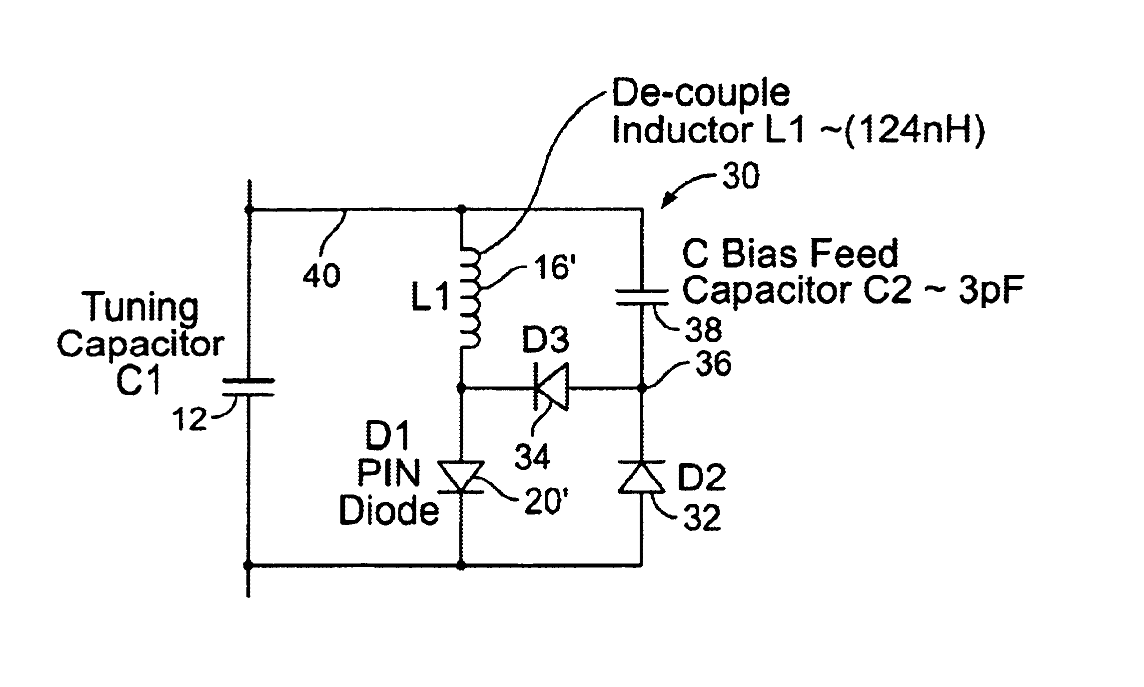
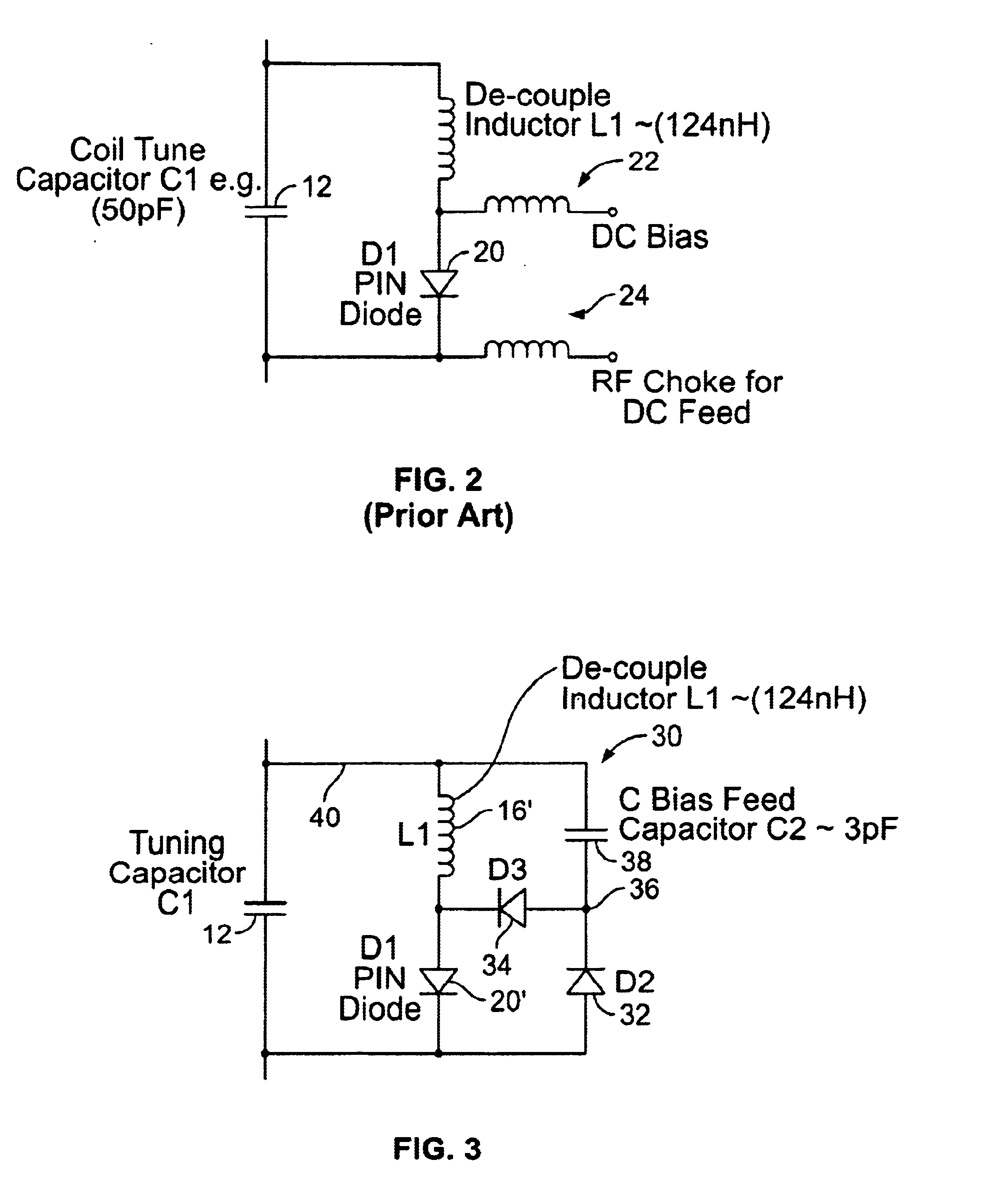
Referring to FIG. 3, an auto-bias detuning circuit 30 includes a detuning inductor 16′ and PIN diode 20′ (or other suitably “slow” diode) in parallel with the tuning capacitor 12. Switching diodes 32, 34 (or other diodes that can switch at the RF frequency) are connected in parallel with the PIN diode 20′. The common node 36 of the diodes 32, 34 is connected through a bias capacitor 38 to the detuning inductor node 40 of the capacitor 12. The diodes 20′, 32, 34 are arranged with the same polarity with respect to a serial path through the diodes 20′, 32, 34.

In normal operation, the RF voltages and currents in the coil 10 are on the order of hundreds of volts and several amperes, so it is feasible to take a small fraction of the available power for conversion to DC to forward bias the PIN diode 20′. This small power drain is much smaller than the power turned into heat by the switching losses in a normal passive de-coupler. During the negative going RF cycle, current flows through the...


PUM


Abstract

A detuning circuit for an MRI coil having a series tuning capacitor includes: a detuning inductor and a PIN diode in parallel communication with the tuning capacitor, where the tuning capacitor has a tuning inductor node and a PIN diode node; a first diode and a second diode in parallel communication with the PIN diode, where the first, second and PIN diodes are arranged with the same serial polarity and the first and second diodes have a common node; and a reactance in communication between the common node and the tuning inductor node. The circuit detunes the MRI coil in response to an MRI transmit pulse. A detuning circuit for an MRI coil having a series tuning capacitor includes a detuning inductor; and a detuning switch in parallel combination with a secondary tuning capacitor, the detuning inductor and the parallel combination being in parallel communication with the series tuning capacitor. The secondary tuning capacitor acts to reduce current during detuning of the MRI coil.

Description

BACKGROUND OF THE INVENTIONThe present invention relates to magnetic resonance imaging systems, and particularly to the radio frequency coils used in such systems.Magnetic resonance imaging (MRI) utilizes hydrogen nuclear spins of the water molecules in the human body, which are polarized by a strong, uniform, static magnetic field of the magnet (named B0—the main magnetic field in MRI physics). The magnetically polarized nuclear spins generate magnetic moments in the human body. The magnetic moments are aligned parallel to the direction of the main magnetic field, B0, in a steady state, and produce no useful information if they are not disturbed by any excitation.The generation of a nuclear magnetic resonance signal (NMR) for MRI data acquisition is accomplished by applying a uniform radio frequency (RF) magnetic field (named the B1 field or the excitation field) orthogonal to B0. This RF field is centered on the Larmor frequency of protons in the B0 field and causes the magnet mom...

Claims


Application Information

Patent Timeline
IPC IPC(8): G01R33/32G01R33/36
CPCG01R33/3657G01R33/3628
Inventor BURL, MICHAELZOU, MARK XUEMING
Owner GENERAL ELECTRIC CO
Why Eureka
Try Eureka