Runway obstacle detection system and method

a detection system and obstacle technology, applied in the field of runway obstacle detection system, can solve the problems of system disadvantage and insufficient infrastructure suppor

Inactive Publication Date: 2005-02-01
ROCKWELL COLLINS INC
View PDF10 Cites 115 Cited by
  • Summary
  • Abstract
  • Description
  • Claims
  • Application Information

AI Technical Summary

Problems solved by technology

In many situations, such as in underdeveloped areas, for example, in third world countries, or small airports and the like, there may not be sufficient infrastructure to support tagging each cart with a transponder and having an approp

Method used


Image

  • Runway obstacle detection system and method
  • Runway obstacle detection system and method
  • Runway obstacle detection system and method

Examples


Embodiment Construction

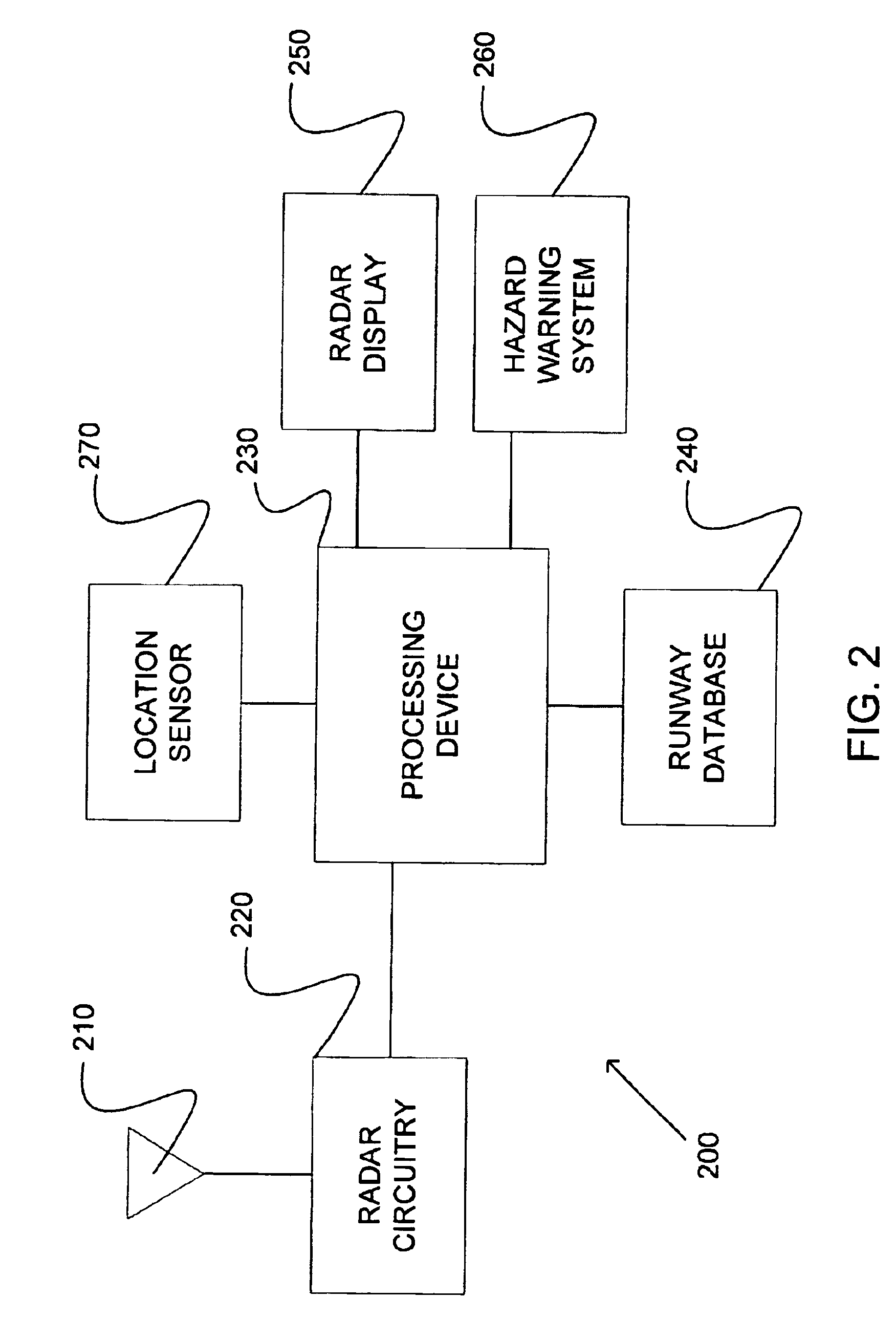
Before describing in detail the particular improved system and method, it should be observed that the invention includes, but is not limited to a novel structural combination of conventional data / signal processing components and sensing circuits, and not in the particular detailed configurations thereof. Accordingly, the structure, methods, functions, control and arrangement of conventional components and circuits have, for the most part, been illustrated in the drawings by readily understandable block representations and schematic diagrams, in order not to obscure the disclosure with structural details which will be readily apparent to those skilled in the art, having the benefit of the description herein. Further, the invention is not limited to the particular embodiments depicted in the exemplary diagrams, but should be construed in accordance with the language in the claims.

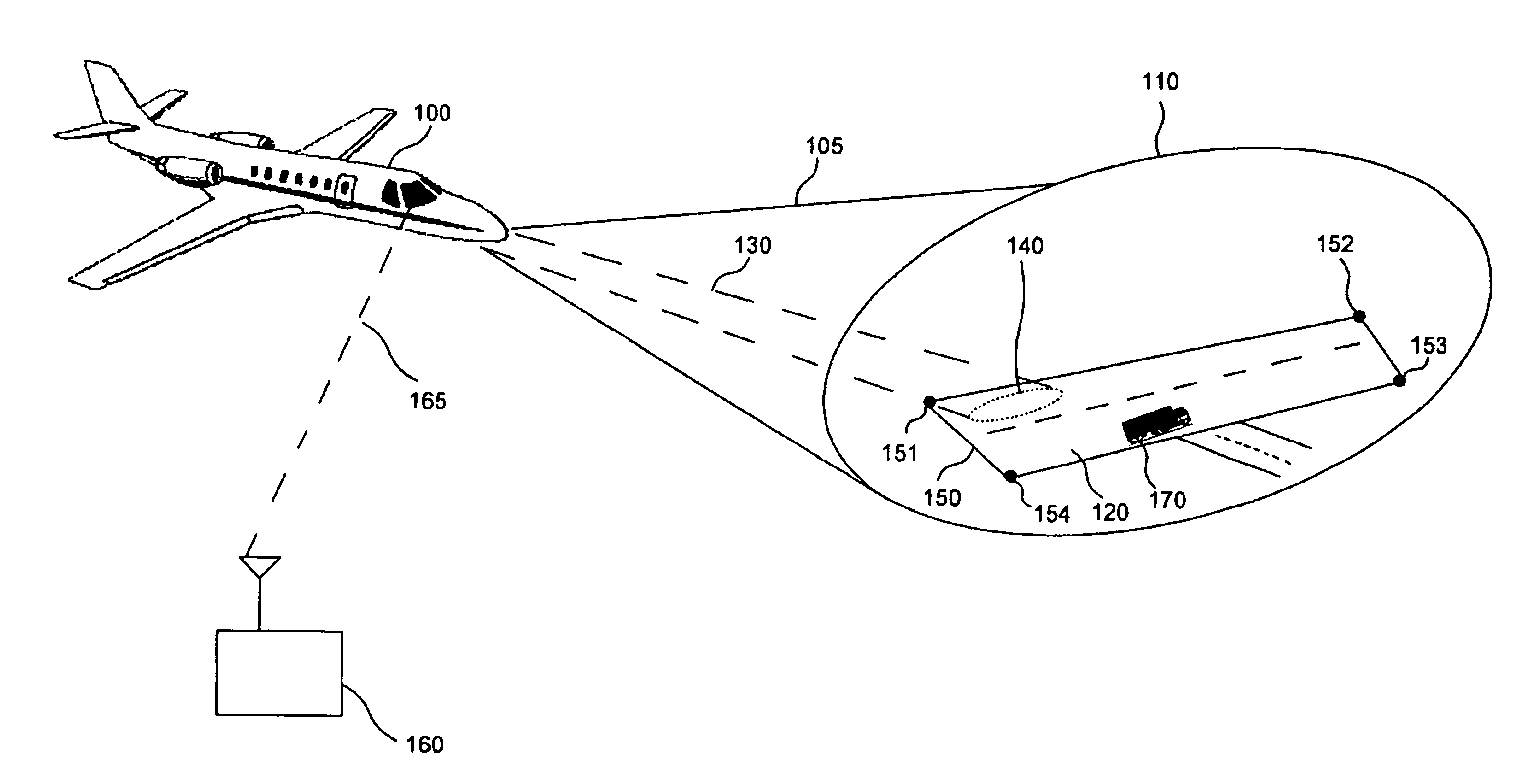
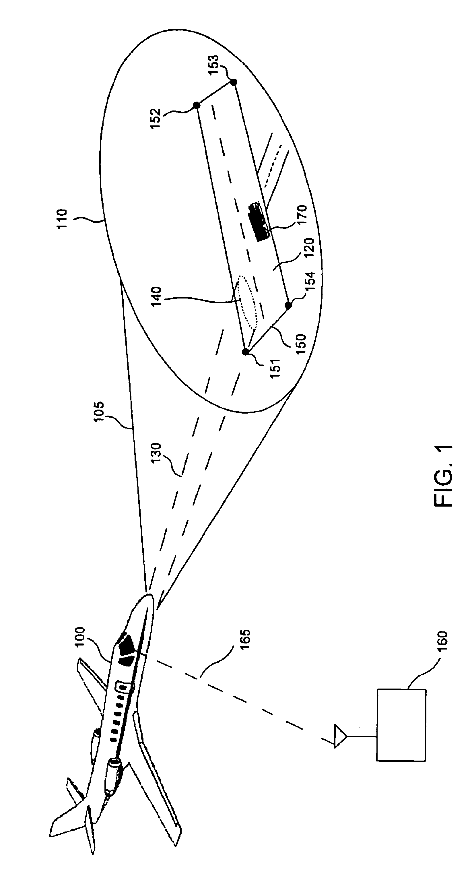
Referring now to FIG. 1, an aircraft 100, such as an airplane or other flying vehicle may have on-board an...


PUM


Abstract

An airborne radar system is disclosed. The airborne radar system comprises a radar antenna, radar circuitry coupled to the radar antenna, and a runway database comprising runway location information. The airborne radar system also comprises a processing device retrieving from the runway database, runway location information for a runway being approached by an aircraft, based on the location of the aircraft, and directing a radar beam defined by a polygon which represents the runway and which is derived from the runway information, the processing device determining whether there are any obstacles on the runway.

Description

BACKGROUNDThe invention relates generally to a sensor system for detecting obstacles on a runway. Further, the invention relates to an airborne radar or other airborne sensor system which is capable of detecting obstacles on a runway when an aircraft is in a landing mode or in a taxi mode. More particularly, the invention relates to an airborne radar or other airborne sensor system that is capable of detecting obstacles within a defined region which is representative of the runway, the defined region being retrieved from a runway database.In conventional runway obstacle detection systems, land based radar systems are used to detect runway obstacles. In another conventional runway obstacle detection system, objects which may enter a runway, such as baggage carts, runway tugs, other aircraft, emergency vehicles, maintenance vehicles, etc., may carry transponders which provide location information such as generated from a GPS receiver. The transponders may relay information to a centra...

Claims


Application Information

Patent Timeline
IPC IPC(8): G01S13/00G01S13/93G01S13/86G01S19/15
CPCG01S13/93G01S13/86
Inventor WOODELL, DANIEL L.
Owner ROCKWELL COLLINS INC
Why Eureka
Try Eureka