Central office interface techniques for digital subscriber lines

a technology of central office and subscriber line, applied in the field of telecommunications, can solve problems such as the ringing of the telephone, and achieve the effects of reducing the physical space needed to house the central office circuitry, reducing the cost of materials, manufacturing, deployment and maintenance, and reducing the physical spa

Inactive Publication Date: 2005-02-01
IKANOS COMMUNICATIONS
View PDF75 Cites 14 Cited by
  • Summary
  • Abstract
  • Description
  • Claims
  • Application Information

AI Technical Summary

Benefits of technology

The techniques described here provide a splitterless central office interface for digital subscriber lines. One benefit of the techniques provided is that the amount of physical space needed to house the central office circuitry is reduced. Another benefit is that the costs associated with materials, manufacturing, deployment and maintenance are reduced.

Problems solved by technology

This causes a telephone set to ring.

Method used


Image

  • Central office interface techniques for digital subscriber lines
  • Central office interface techniques for digital subscriber lines
  • Central office interface techniques for digital subscriber lines

Examples


Embodiment Construction

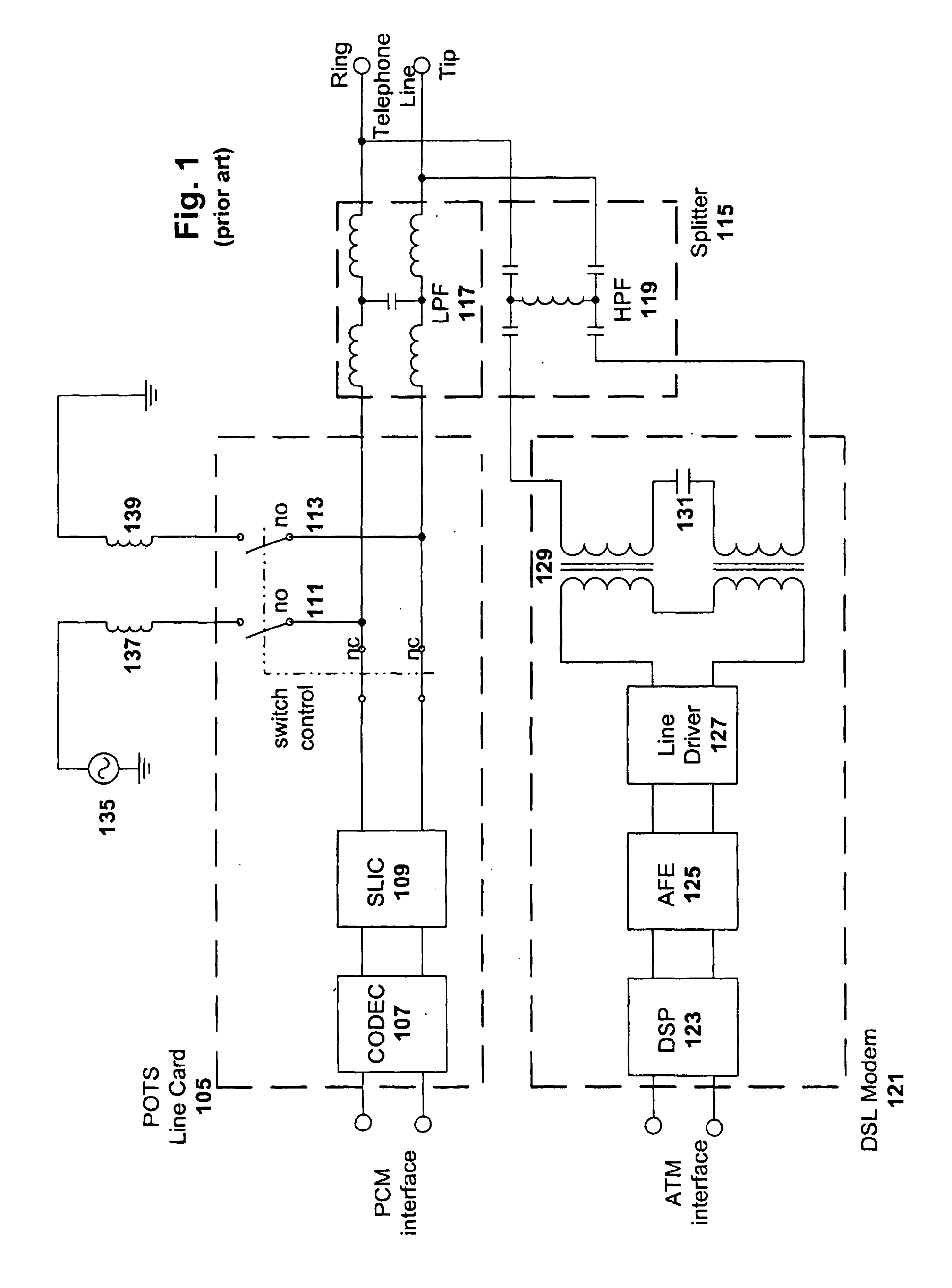
FIG. 1 is a block diagram of a conventional central office interface for a digital subscriber line. The interface includes splitter 115, POTS line card 105 and DSL modem 121. Additionally included is a ringing circuit comprised of source 135, inductor 137 and inductor 139.

Splitter 115 is a conventional passive splitter and is used to couple the telephone line with the POTS line card 105 and the DSL modem 121. The splitter 115 is comprised of a low pass filter 117 and a high pass filter 119. Low pass filter 117 isolates the low frequency POTS signal (e.g., voice and fax data under 4 KHz) from the incoming telephone line, and provides that POTS signal to the POTS line card 105. High pass filter 119 isolates the high frequency DSL signal from the incoming telephone line, and provides that DSL signal to the DSL modem 121. Each of these filters can be implemented in a number of ways to be compliant with applicable splitter specifications. For example, low pass filter 117 can be a 5-pole ...


PUM


Abstract

A splitterless interface between a digital subscriber line (DSL) and the central office equipment that can receive and isolate the low frequency voice data and high frequency digital data from a telephone line. This interface can also mix and transmit low frequency voice data and high frequency digital data onto a telephone line. For POTS band frequencies, a reactive impedance coupled across the two-wire interface of the POTS line card, and serially coupled to the line side of the DSL coupling transformer, has an open state magnitude. The magnitude of the line side windings of the DSL coupling transformer is low at POTS band frequencies. POTS band signal power is therefore delivered to the POTS line card. For DSL band frequencies, the reactive impedance across the two-wire interface of the POTS line card has a closed state magnitude. The POTS line card is therefore essentially short-circuited at DSL band frequencies, and DSL band signal power is delivered to the DSL modem. The frequency band in which the reactive impedance transitions from an open state magnitude to a closed state magnitude corresponds to the frequency band between the POTS frequency band and the DSL frequency band.

Description

BACKGROUND OF THE INVENTION1. Field of the InventionThe invention relates to telecommunications, and more particularly, to a digital subscriber line interface between a telephone line and central office equipment of a network operator providing voice and digital subscriber services.2. Description of the Related ArtThe demand for more bandwidth on existing conventional telephone lines increases as more customers send and receive digital data over telephone lines. In general, a conventional telephone line is comprised of a pair of copper conductors that connect a telephone set to the nearest central office, digital loop carrier equipment, remote switching unit or any other equipment serving as the extension of the services provided by the central office. This pair of copper conductors, which is also referred to as a twisted pair, has its leads named as tip and ring. The tip and ring nomenclature is derived from the electrical contacts of an old-style telephone plug. Replacing these ex...

Claims


Application Information

Patent Timeline
Patent Type & Authority Patents(United States)
IPC IPC(8): H04M11/06
CPCH04M11/062
Inventor MOHAJERI, HESSAMKIYKIOGLU, SERDARBABAEI, HERON
Owner IKANOS COMMUNICATIONS
Why Eureka
Try Eureka