Power-controlled bed and method for controlling operations thereof

a power-controlled bed and bed frame technology, applied in the field of power-controlled beds, can solve the problems of not being dynamically shifted between two or more position combinations, not being adjusted to a considerable large angle of elevation, and bed and sickbeds, so as to protect users from stroke, relieve varicose vein symptoms, and promote blood circulation

Inactive Publication Date: 2005-02-08
WANG YI LUNG
View PDF7 Cites 49 Cited by
  • Summary
  • Abstract
  • Description
  • Claims
  • Application Information

AI Technical Summary

Benefits of technology

The following are some of the functions that could be achieved through the raising and the lifting mechanisms of the power-controlled bed of the present invention:a. The movable back rest part, the thigh rest part, and the leg rest part of the mattress of the bed could be flattened at the same time to a horizontal position by manually controlling the raising mechanism, so that the bed could be used as a general horizontal bed.b. The movable back rest part, the thigh rest part, and the leg rest part of the mattress of the bed could be adjusted to different angles of elevation by manually controlling the raising mechanism, so that a user could lie on the bed in the most comfortable position.c. The upper bed frame could be adjusted to different heights and inclinations within a large range by manually controlling the lifting mechanism.d. The upper bed frame could be statically or dynamically shifted between two or more heights and inclinations through automatic operation of the lifting mechanism set by pushing keys on the controller, so that a user may have multiple choices in operating the bed;e. The lifting mechanism could be manually operated to adjust the upper bed frame to a large angle of elevation suitable for a patient suffering from a lung-related disease to clear sputum from the chest easily. Means may be provided to work with the lifting mechanism to prevent the patient from slipping downward on the inclined bed.f. The lifting mechanism could be manually operated to adjust the upper bed frame to a large angle of elevation suitable for supplying sufficient oxygen to the user's brain and relieving symptoms of varicose veins, hemorrhoids, gastroptosis, and compressed spine that are in connection with the force of gravity when the user is lying on the bed with the head pointed downward.g. When the bed is set to automatically shift between two or more selected position combinations within a set operating time, the upper bed frame is dynamically, repeatedly, and alternately shifted between the selected modes to well utilize the force of gravity to alternately change positions of the user's head and feet, in order to promote the user's blood circulation and protect the user from a stroke.h. When the bed is set to a dynamic state being automatically operated in a continuous manner, it functions like a cradle to help the user to get to sleep.i. When the bed is set to a random state being automatically operated in a continuous manner, it helps to distract the user's attention due to the unpredictable movements of the bed and thereby temporarily relieves the user from constant pressure.j. When the bed is in a medium height and the lifting mechanisms are held in a stopped state, the crank pivoting means may be actuated for the bed to reciprocatingly translate and thereby swing forward and backward within the range of movement of the bed in a horizontal position.

Problems solved by technology

All the above-mentioned leisure beds and sickbeds, which are either prior art or laid open, could not be adjusted to a considerably large angle of elevation, and could not be dynamically shifted between two or more position combinations.
Furthermore, the conventional power-controlled beds for medical treatment and rehabilitation purposes, including those of the prior art and that disclosed in the inventor's Taiwan Patent Publication No. 372863, include complicate structures and are therefore too expensive to be widely accepted by most consumers.

Method used


Image

  • Power-controlled bed and method for controlling operations thereof
  • Power-controlled bed and method for controlling operations thereof
  • Power-controlled bed and method for controlling operations thereof

Examples


first embodiment

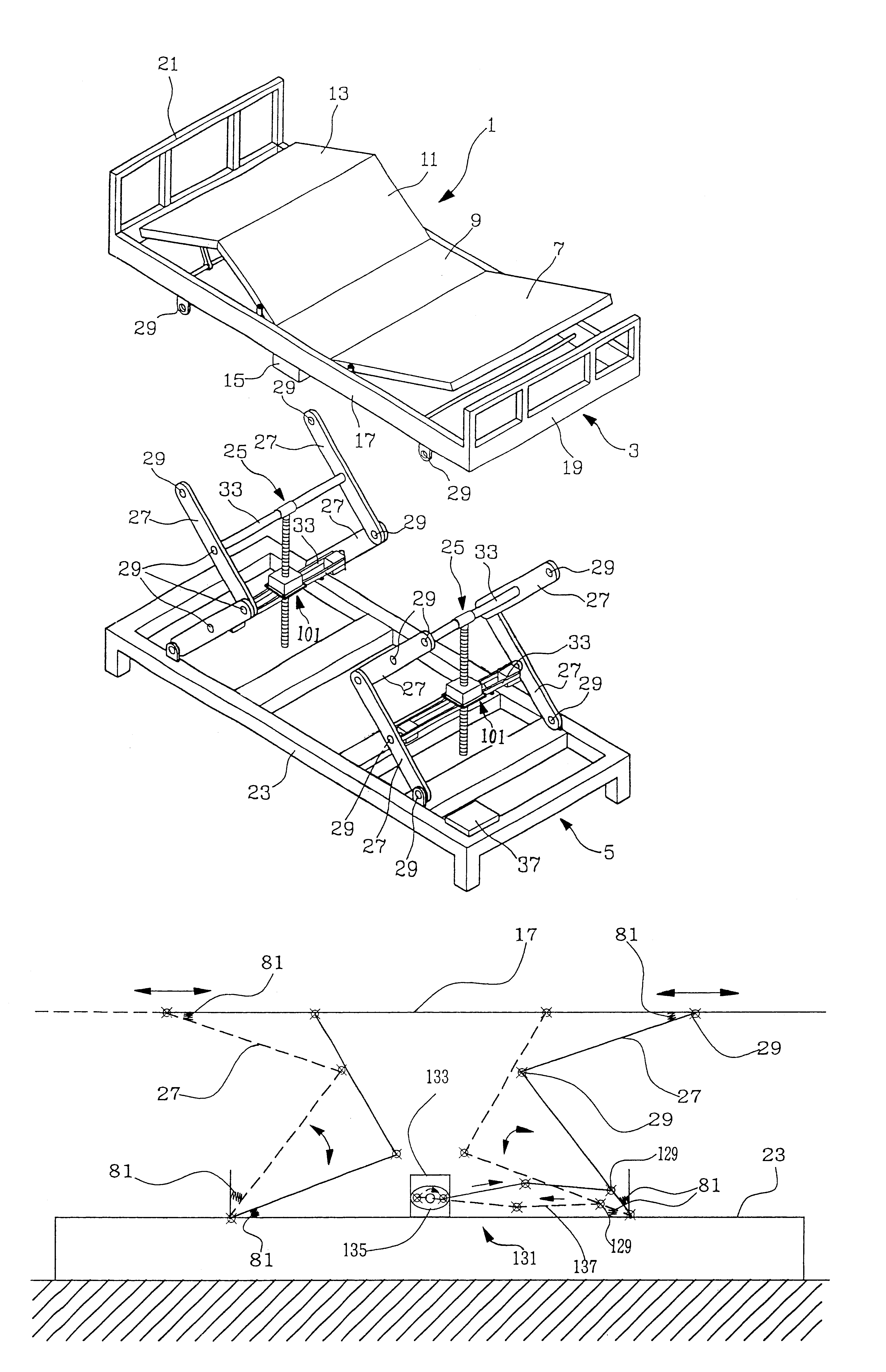
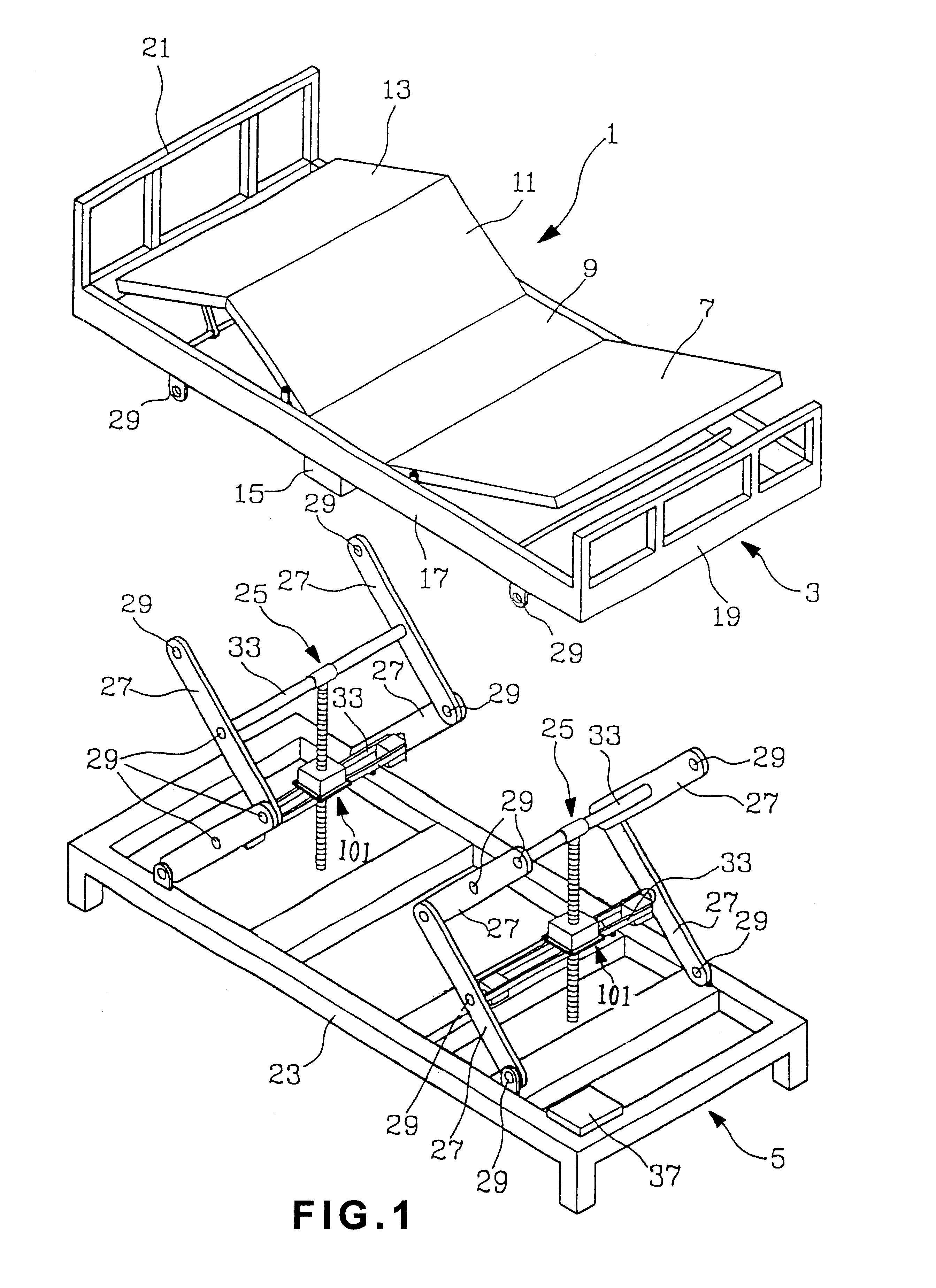
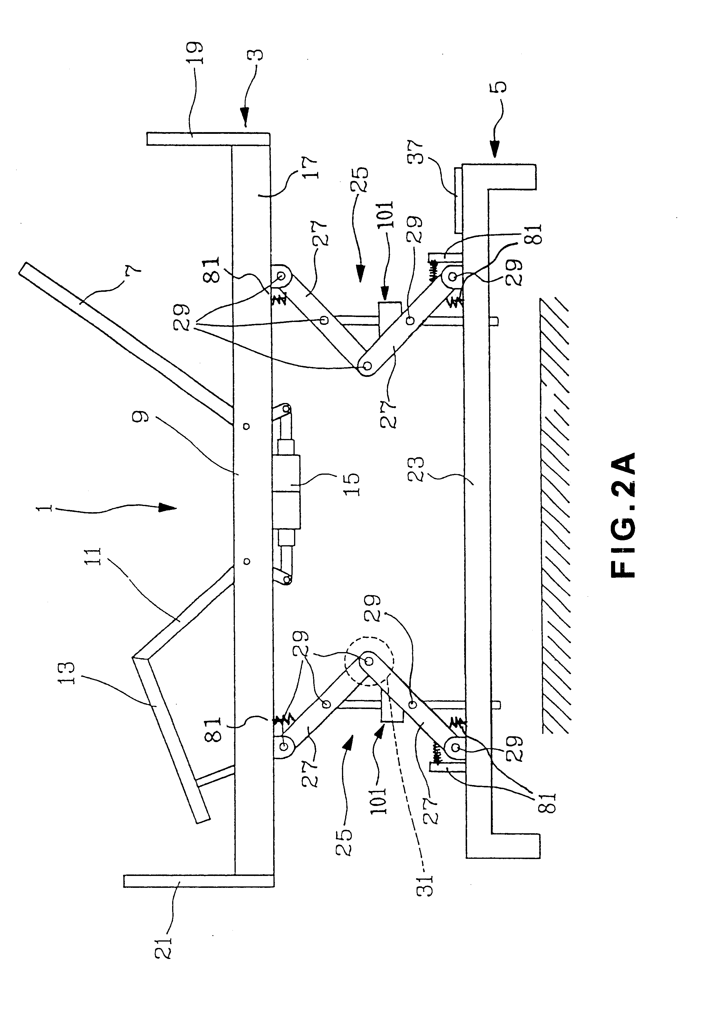
Please refer to FIGS. 1, 2A, and 2B. The power-controlled bed 1 according to the present invention includes a top structure 3 and a chassis structure 5. The top structure 3 includes a mattress divided into four parts, namely, a movable back rest part 7, a fixed hip rest part 9, a movable thigh rest part 11, and a movable leg rest part 13; and an upper bed frame 17 for supporting the mattress thereon. Two conventional mattress raising mechanisms 15 are mounted below the fixed hip rest part 9 to separately adjust an angle of elevation of the back rest part 7 relative to the upper bed frame 17 and arch or flatten the thigh rest part 11 and the leg rest part 13 that are pivotally connected to each other. The top structure 3 also includes a protective headboard 19 and a protective footboard 21.

The chassis structure 5 includes a lower bed frame 23, on which a front and a rear lifting mechanism 25 are mounted. Each of the two lifting mechanisms 25 includes two pairs of upper and lower cran...

second embodiment

Please refer to FIGS. 3, 4A, and 4B. The power-controlled bed 1 according to the present invention includes an upper bed frame 17 and a chassis structure 5 consisting of a front leg support 43, a lower bed frame 23, and a rear leg support 45. The upper bed frame 17 is pivotally connected near a lower front end to upper ends of the front leg support 43 of the chassis structure 5 via fixed pivot joints 41, and near a lower rear end to a lifting mechanism 25 mounted near a middle portion of the lower bed frame 23. The lifting mechanism 25 includes a pair of upper and lower cranks 27. The upper and the lower cranks 27 are connected at inner ends to each other by first pivot joints 29 and at outer ends to corresponding positions on rear portions of the upper and the lower bed frames 17 and 23, respectively, via second pivot joints 29. An upper and a lower crossbar 33 are extended between and connected to the upper and the lower cranks 27, respectively. A vertical or a horizontal threaded...


PUM


Abstract

A power-controlled bed mainly includes an upper bed frame on which a mattress divided into movable back, thigh, and leg rest parts and a fixed hip rest part is supported; a lower bed frame; at least one lifting mechanism pivotally connected at upper and lower ends to the upper and the lower bed frames, respectively; and a microcomputer controller for controlling operation of the lifting mechanism. The lifting mechanism may be manually controlled for the upper bed frame to statically stay at different positions, or be automatically controlled via the controller to dynamically shift the upper bed frame between two or more selected position combinations, so that the force of gravity is well utilized in the movements of the bed to promote a user's blood circulation, help clearing of sputum, enable sufficient supply of oxygen to the brain, do rehabilitation exercises, etc.

Description

BACKGROUND OF THE INVENTION1. Field of the InventionThe present invention relates to a power-controlled bed, and more particularly to a power-controlled bed having an upper bed frame adapted to statically stay at a selected position or dynamically shift between two or more selected position combinations through manual or automatic control, so that the bed could be used in homes, hotels, recreation centers, hospitals and other health-care centers in the form of furniture or medical instrument. The present invention also relates to a method for controlling operations of the power-controlled bed.2. Description of the Prior ArtThere are many types of power-controlled beds known in the prior art. The following are some examples of these conventional power-controlled beds:a. Taiwan New Utility Model Patent Application No. 87218307 laid open under Patent Publication No. 370869 entitled “A Power-controlled Bed” discloses a power-controlled bed for leisure purpose, a back-resting portion and...

Claims


Application Information

Patent Timeline
Patent Type & Authority Patents(United States)
IPC IPC(8): A61G7/012A61G7/015A61G7/002A61G7/005
CPCA61G7/015A61G7/012A61G7/005
Inventor WANG, YI-LUNG
Owner WANG YI LUNG
Why Eureka
Try Eureka