Method for installing blind threaded inserts

a control method and insert technology, applied in the direction of threaded fasteners, force/torque/work measurement apparatus, instruments, etc., can solve the problems of increasing the complexity of spin-pull tools, and increasing the cost of spin-pull tools. , the installation of parts with thick walls is not easy, and the installation of parts is difficul

Active Publication Date: 2005-02-08
PEM MANAGEMENT INC
View PDF12 Cites 19 Cited by
  • Summary
  • Abstract
  • Description
  • Claims
  • Application Information

AI Technical Summary

Benefits of technology

When an error message is present, the affected unit is typically identified as possibly non-conforming and segregated for further review. The present invention offers a significant advantage in the case of an error or fault condition in that there is a greater probability that the insert was installed properly and the unit will not require rework. This is because

Problems solved by technology

However, because the upset force they can develop is limited, they generally cannot be used to install parts having thicker walls.
Spin-pull tools are more complex and consequently more expensive and heavier than spin-spin tools.
They are also more difficult to set up and require more maintenance.
Both types of tools require time-consuming set-up steps with some degree of trial and error and a skilled operator.
The set-up requirements of either type of tool represent lost time and require significant operator training.
Although spin-pull tools are the better choice for thick

Method used


Image

  • Method for installing blind threaded inserts
  • Method for installing blind threaded inserts
  • Method for installing blind threaded inserts

Examples


Embodiment Construction

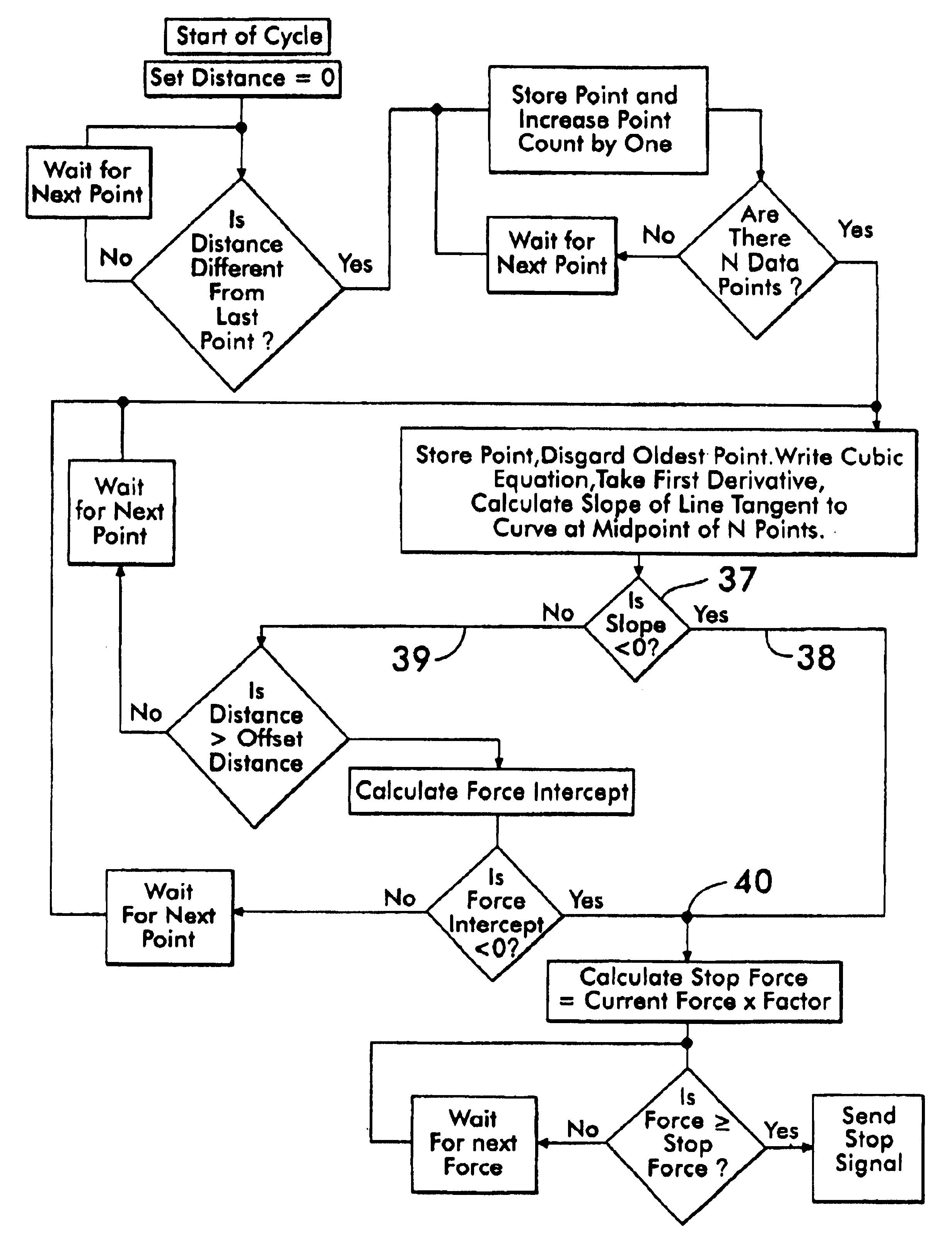
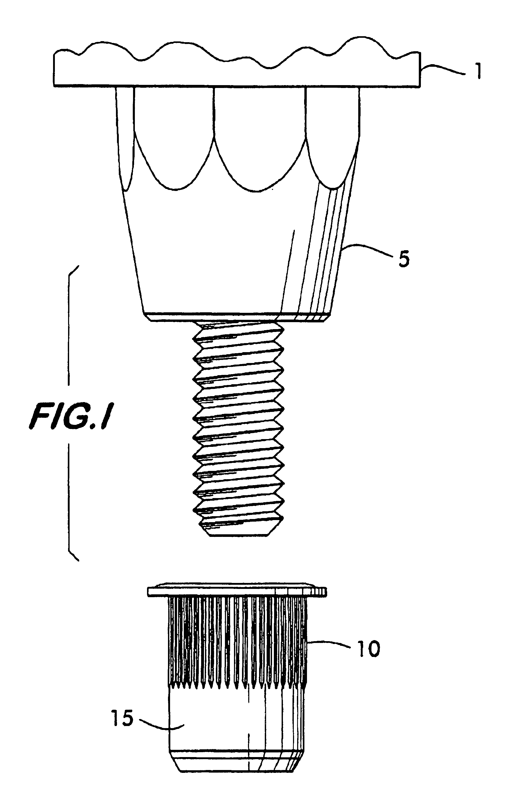
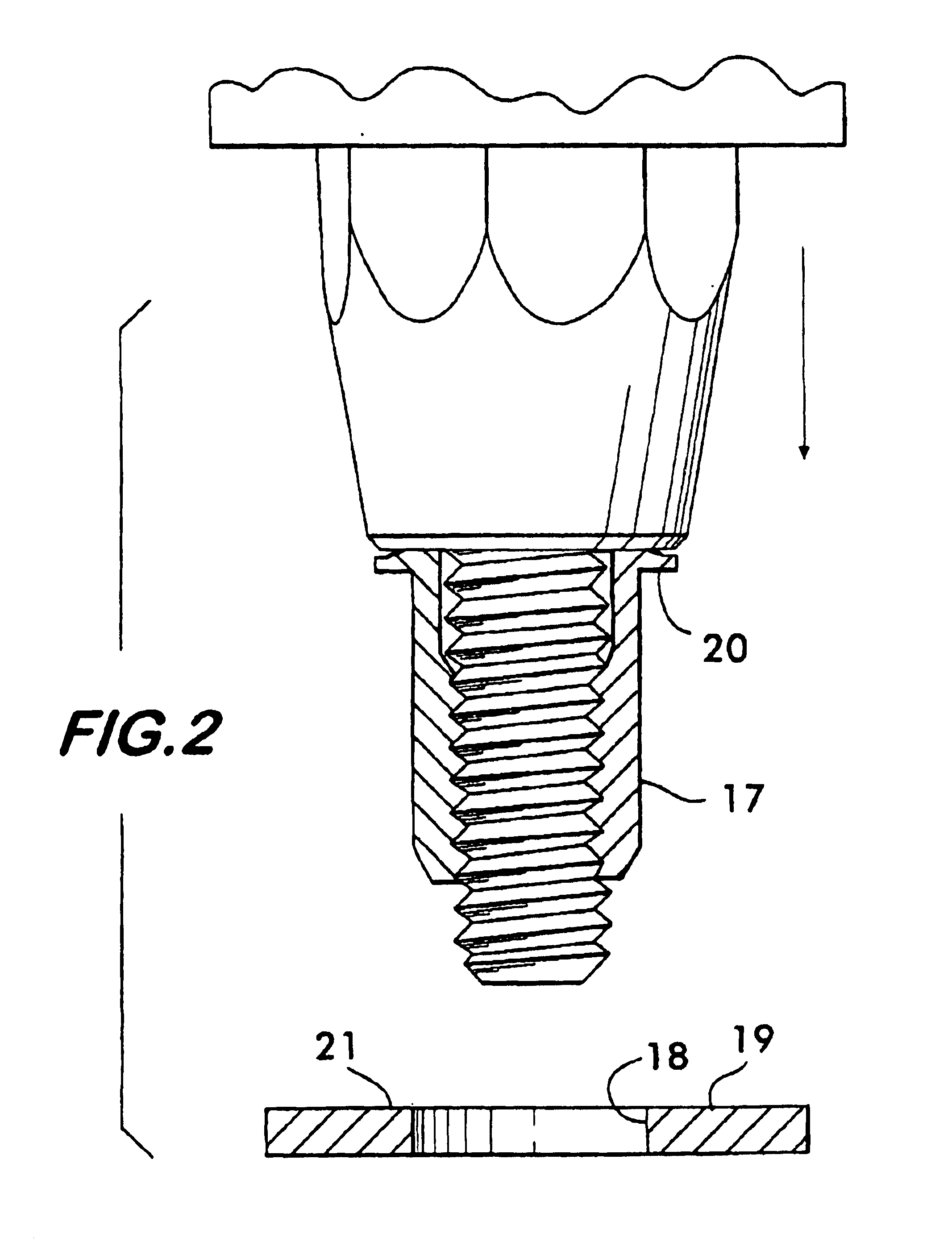
The following operational sequence is an overview of the operation of the preferred embodiment of the invention and assumes a tool head mounted to the end of a robot arm. The sequence for a hand held tool manipulated by an operator is essentially the same. In the preferred embodiment shown in FIGS. 1-4, the pulling force is applied as many similar prior art hand tools by a hydraulic cylinder, it being understood that the control system of the invention may be applied to available tools of this type.

Referring first to FIG. 1, the insert head support means 5 is adjustably attached to the body of the hydraulic cylinder 1. A threaded mandrel 6 extends from the support. The sequence of operation of the preferred embodiment begins with the mandrel in the fully extended state as shown in FIG. 1. An insert 10 supported by a means not shown is in correct radial position, but is axially removed from the mandrel 6. The first action required is the rotation of the mandrel in the direction requi...


PUM

PropertyMeasurementUnit
Forceaaaaaaaaaa

Abstract

A spin-pull blind insert tool utilizes a control system that generates a stop signal based on the relationship between the force values and the motion values derived from the action of the tool mandrel. The improved control system utilizes the shape of the force-deformation curve and not just a given pre-set force value or pull distance. Hence, the control system of the present invention does not require any set-up for changes in panel thickness unless the mandrel is also changed to install a different thread size. This control system develops a force-deformation curve as the fastener is being installed. The stop signal is generated when a pre-set deformation point has been exceeded and the shape of the force curve can be characterized by either of two types. For either type, an algorithm is followed which establishes an optimum stopping point for the installation tool regardless of the panel thickness into which the blind rivet is being installed.

Description

FIELD OF THE INVENTIONThis invention relates to an improved control method for regulating the operation of a hand tool. More specifically, it relates to a hand tool control method for the installation of blind threaded fasteners which deform under a compressive force to grip a panel.BACKGROUND OF THE INVENTIONBlind threaded fasteners are fasteners, either internally or externally threaded, that can be first installed into a hole in a panel with access to one side of the panel only, hence the term “blind”. Most of these fasteners contain three basic components: a head, an intermediate collapsible thin-walled shank, and an internally threaded region at the end. As depicted sequentially in FIGS. 1, 2, 3, and 4, the threaded area and a portion of the shank are first installed into the panel hole and then a compressive force is applied to the shank with a tool by pulling on the threaded region while supporting the head. This compression causes the shank to deform and buckle outwardly, cr...

Claims


Application Information

Patent Timeline
IPC IPC(8): B25B27/00B21J15/00B21J15/28F16B37/04F16B37/06
CPCB21J15/285B25B27/0014F16B37/067Y10T29/53709Y10T29/49764Y10T29/53065Y10T29/49915Y10T29/49938Y10T29/49954Y10T29/49776Y10T403/4966Y10T29/49947Y10T29/49771
Inventor HARLOW, GARYDISE, RONALD S.
Owner PEM MANAGEMENT INC
Why Eureka
Try Eureka