True-joint anchoring systems for cavity walls

Inactive Publication Date: 2005-02-08
HOHMANN & BARNARD INC
View PDF14 Cites 79 Cited by
  • Summary
  • Abstract
  • Description
  • Claims
  • Application Information

AI Technical Summary

Benefits of technology

In general terms, the invention disclosed hereby includes an anchoring system for a cavity wall. The embodiments described hereinbelow all utilize true-joint construction to reduce the height of wall reinforcement and wall anchor combinations, and thereby enable the erection of masonry block backup walls with highly uniform bed joint thicknesses and readily maintained verticality. Both the wall reinforcement and the wall anchor are

Problems solved by technology

On the other hand, contractors find that heavy wire anchors, with diameters approaching the mortar layer height specification, frequently result in misalignment.
Besides earthquake protection, the failure of several high-rise buildings to withstand wind and other lateral forces h

Method used


Image

  • True-joint anchoring systems for cavity walls
  • True-joint anchoring systems for cavity walls
  • True-joint anchoring systems for cavity walls

Examples


second embodiment

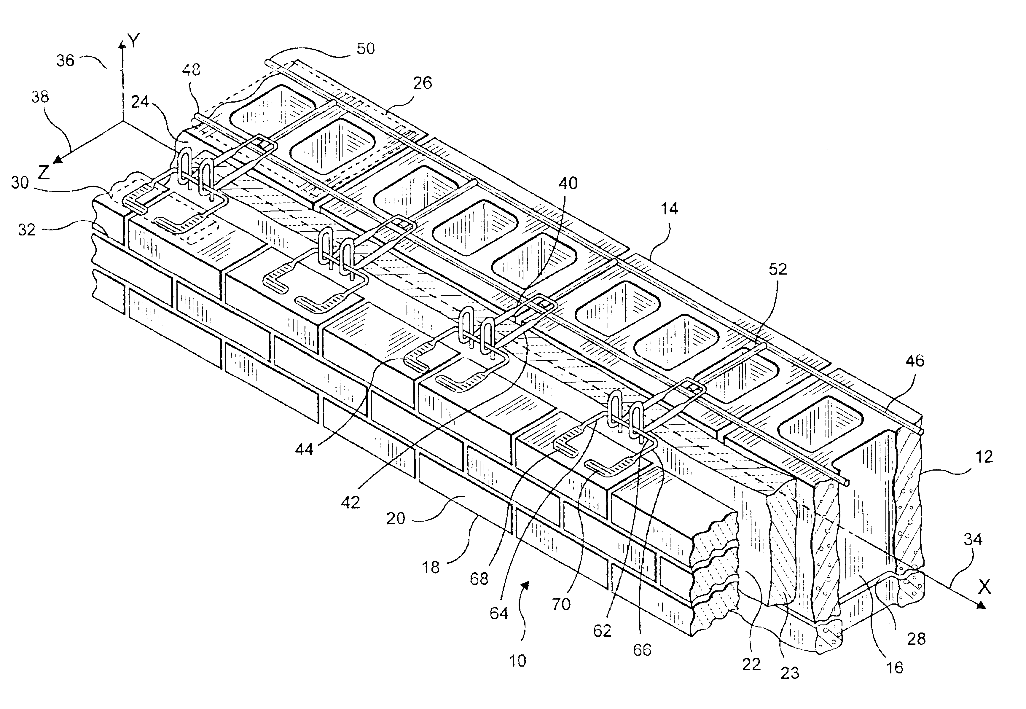
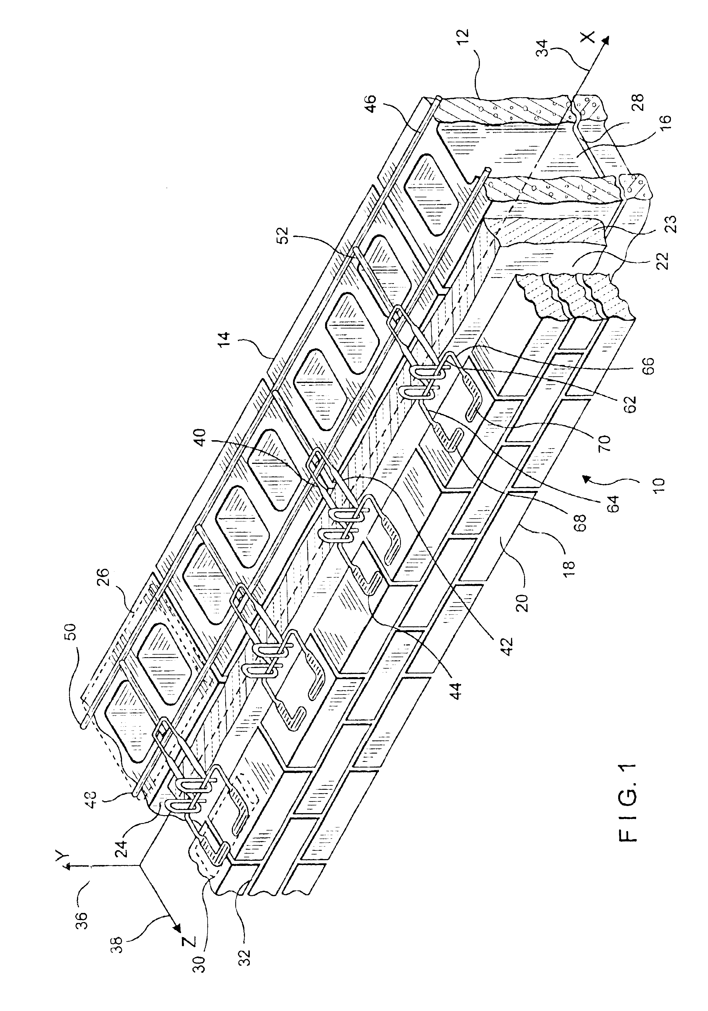
In the second embodiment, and referring now to FIGS. 6 and 7, the details of the wall reinforcement 146 and wall anchor 140 of the above-described arrangement of wire formatives are shown. For the true joint, swaged into side wire 148 of wall reinforcement 146 are indentations 178 and 180 at attachment sites 182 and 184, respectively; and into intermediate wire body indentations 186 at attachment sites 188 and 189.

first embodiment

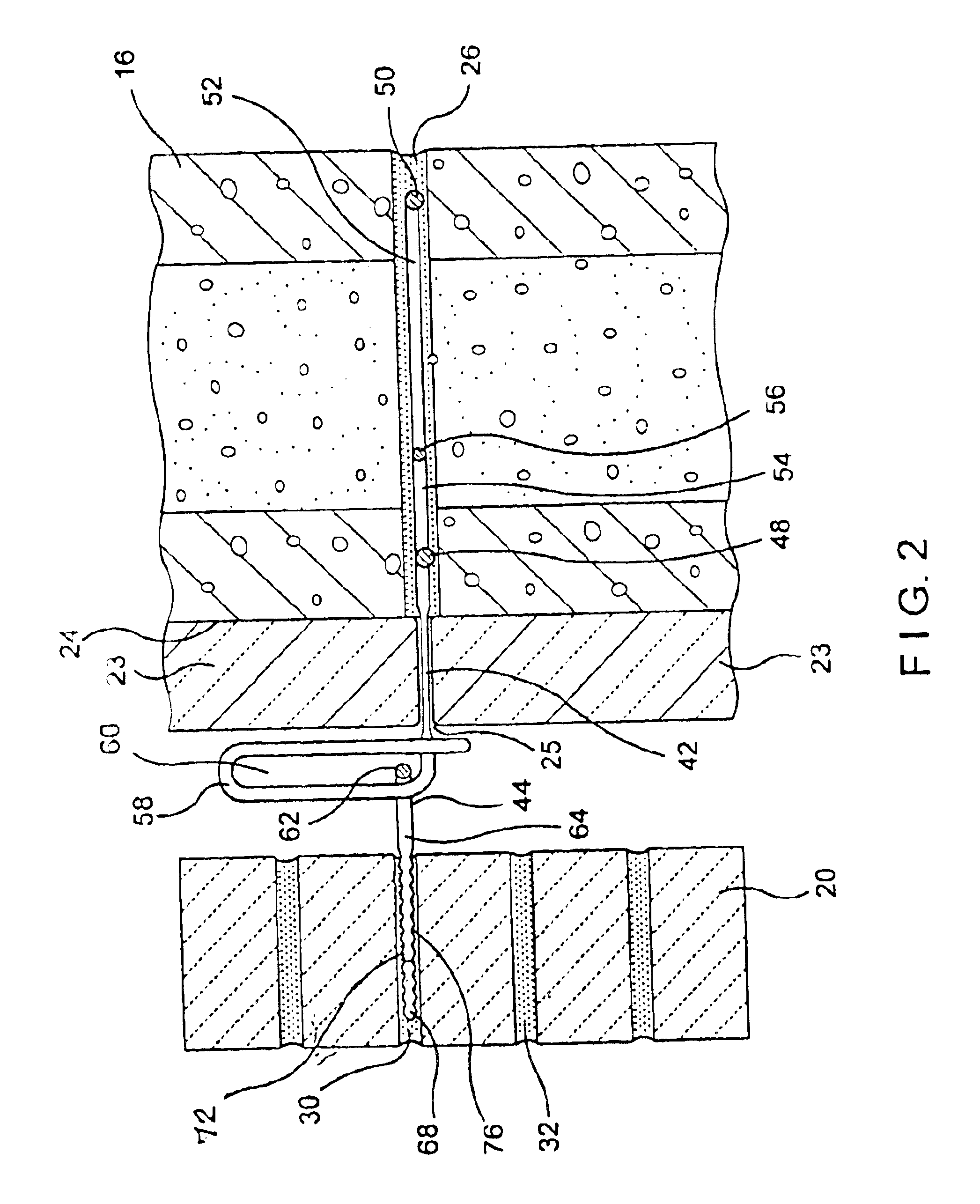
During assembly, the two components—the wall anchor 140 and the wall reinforcement 146—are fusibly joined at attachment sites 182, 184 and 188 and 189 under heat and pressure. Upon assembly, the true joints at the attachment sites 182, 184,188 and 189 have a height no greater than the diameter of the wire of wall anchor 140. Thus, for example, if the 0.187-inch diameter wire is employed for all components, upon insertion of the assemblage into bed joint 126 an equal height of mortar would surround the wall reinforcement 146 and the insertion end of the wall anchor 140. As in the first embodiment, because of the flatness of the combined wall reinforcement and wall anchor assemblage, the ability to maintain verticality of the inner wythe is enhanced.

During the cold working of system components in addition to the swaged indentations, the insertion end of anchor 144 is compressively reduced in height. As described in a prior patent of the present inventors, namely, Hohmann et al., U.S. ...


PUM


Abstract

A high-span anchoring system is described for a cavity wall incorporating a wall reinforcement combined with a wall tie which together serve a wall construct having a larger-than-normal cavity. Further the various embodiments combine wire formatives which are compressively reduced in height by the cold-working thereof. Among the embodiments is a veneer anchoring system with a low-profile wall tie for use in a heavily insulated wall. The compressively reduced in height wall anchors protrude into the cavity through the seams, between insulation strips, which seams seal thereabout and maintain the integrity of the insulation by minimizing air leakage. Further, the eye wires extend across the insulation into the cavity between the wythes, and each accommodates the threading thereinto of a wire facing anchor or wall tie with either a pintle inserted through the eye or the open end of the veneer tie. The veneer tie is then positioned so that the insertion end is embedded in the facing wall. The close control of overall heights permits the mortar of the bed joints to flow over and about the wall reinforcement and wall tie combination inserted in the inner wythe and insertion end of the wall in the outer wythe. Because the wire formatives hereof employ extra strong material and benefit from the cold-working of the metal alloys, the high-span anchoring system meets the unusual requirements demanded thereof.

Description

BACKGROUND OF THE INVENTION1. Field of the InventionThis invention relates to an improved reinforcement structure for cavity walls, and, more particularly, to combined wall anchors and reinforcement trusses or ladders that utilize true-joints to fuse together the components under high heat and high pressure. The resultant anchoring systems meet high flatness requirements facilitating the formation of uniform mortar bed joints. This avoids stackup tolerances and reduces the cutting of blocks to fit within the height requirements. The flatness of the combined wall reinforcement and wall anchor enables the mason to more easily maintain the verticality of the wall.2. Description of the Prior ArtRecently, special attention has been drawn to products that not only improve a mason's productivity, but also aid in straighter joint lines and ultimately better looking buildings. Among these products are cavity wall anchoring systems that tie together backup walls and facing veneers. While the ...

Claims


Application Information

Patent Timeline
IPC IPC(8): E04B1/76E04B1/41
CPCE04B1/7616E04B1/4185
Inventor HOHMANN, RONALD P.HOHMANN, JR., RONALD P
Owner HOHMANN & BARNARD INC
Why Eureka
Try Eureka