Vibratory transducer

Inactive Publication Date: 2005-02-08
ENDRESS HAUSER FLOWTEC AG
View PDF0 Cites 38 Cited by
  • Summary
  • Abstract
  • Description
  • Claims
  • Application Information

AI Technical Summary

Benefits of technology

One advantage of the invention is that, on the one hand, the transducer is very well balanced despite possible operation-dependent variations of the internal mass distribution, and thus also independently of the density of the fluid, namely exclusively as a result of its internal geometry forced by means of cantilevers, whereby internal transverse impulses and transverse forces can be largely kept away from the connected pipe. On the other hand, the internal deformation forces necessary therefor essentially do not act beyond the transducer, particularly

Problems solved by technology

A significant disadvantage of such transducers consists in the fact that as a result of alternating lateral deflections of the vibrating single flow tube, transverse forces oscillating at the same frequency can act on the pipe, and that so far it has been possible to counterbalance these transverse forces only in a very limited manner and with a very large amount of technical complexity.
A big disadvantage of such a transducer is, however, that the antivibrator mass required to achieve sufficien

Method used


Image

  • Vibratory transducer
  • Vibratory transducer
  • Vibratory transducer

Examples


Embodiment Construction

While the invention is susceptible to various modifications and alternative forms, exemplary embodiments thereof have been shown by way of example in the drawings and will herein be described in detail. It should be understood, however, that there is no intent to limit the invention to the the particular forms disclosed, but on the contrary, the intention is to cover all modifications, equivalents, and alternatives falling within the spirit and scope of the invention as defined by the intended claims.

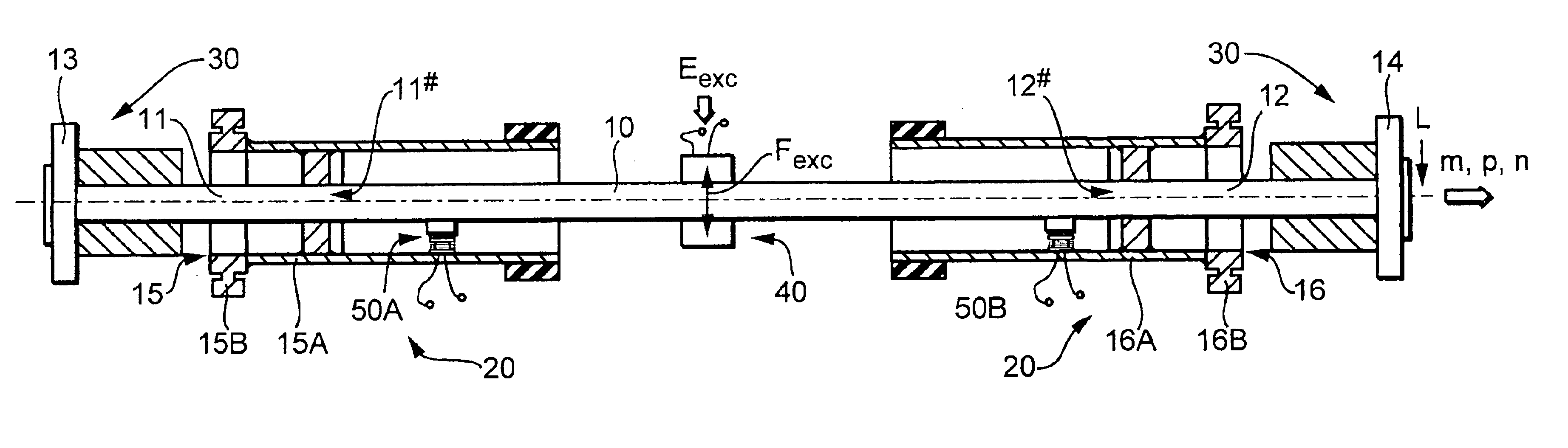
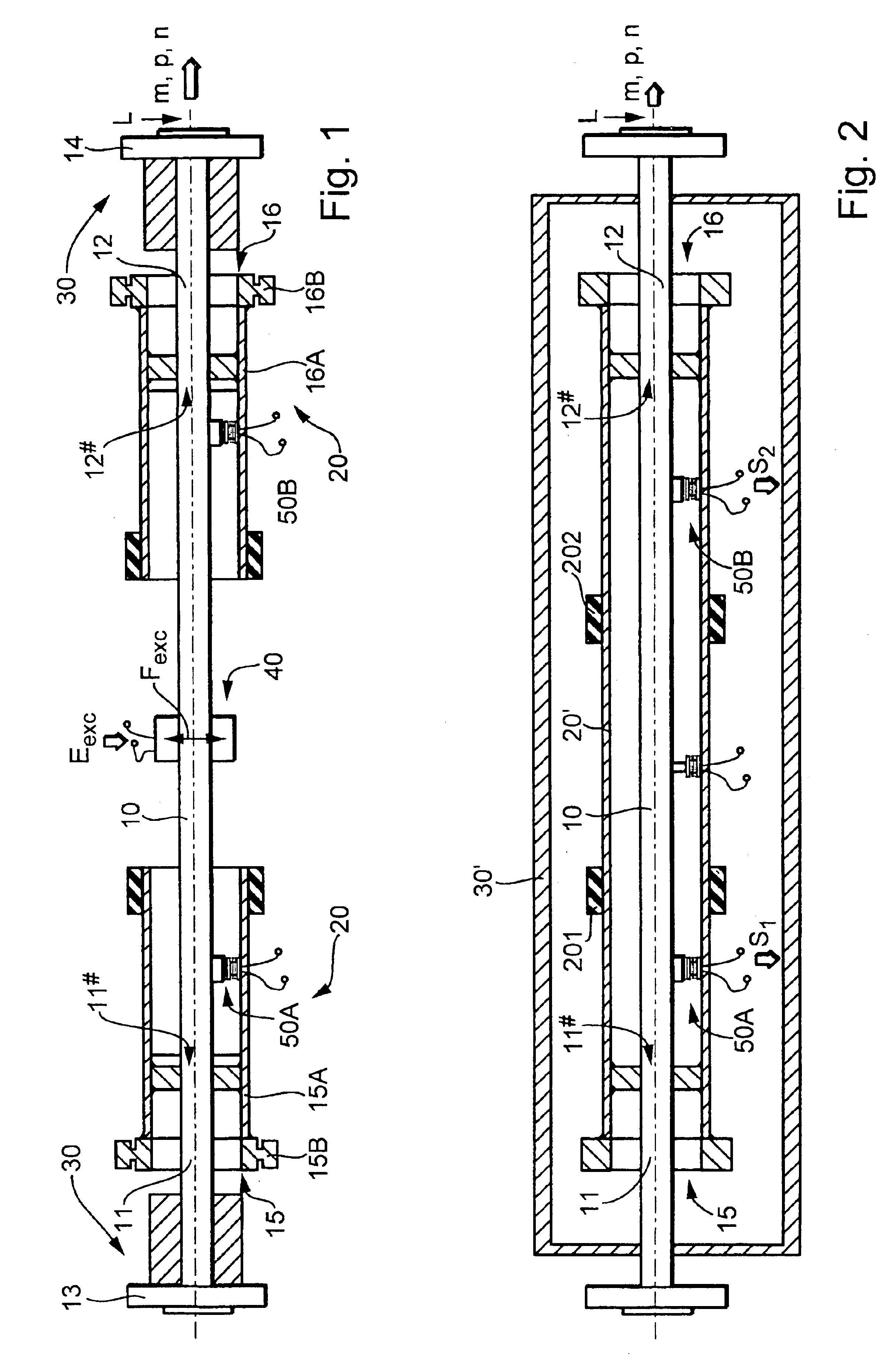
FIGS. 1 and 2 show a vibratory transducer in schematic side views. The transducer serves to produce in a fluid passing therethrough mechanical reaction forces, such as mass-flow-rate-dependent Coriolis forces, density-dependent inertial forces, and / or viscosity-dependent friction forces, which react on the transducer and are measurable, particularly with sensor technology. From these reaction forces, a mass flow rate m, a density ρ, and / or a viscosity η of the fluid, for example, can th...


PUM


Abstract

To conduct a fluid, the transducer has a flow tube which in use is vibrated by an excitation system and whose inlet-side and outlet-side vibrations are detected by means of a sensor system. In response to transverse forces produced in the vibrating flow tube, the latter is, at least temporarily, laterally displaced from an assigned static rest position. To improve the dynamic balance of the transducer, a first cantilever and a second cantilever are rigidly fixed to an inlet-side tube section and an outlet-side tube section, respectively. By means of the cantilevers, the inlet-side and outlet-side tube sections are deformed as a result of lateral displacements of the flow tube. This produces counterforces which at least partially counterbalance the transverse forces produced in the vibrating flow tube. One advantage of the proposed transducer is that it is well balanced even during variations in fluid density.

Description

FIELD OF THE INVENTIONThis invention relates to a vibratory transducer which is particularly suited for use in a Coriolis mass flowmeter.BACKGROUND OF THE INVENTIONTo determine the mass flow rate of a fluid flowing in a pipe and particularly of a liquid, use is frequently made of measuring devices which induce Coriolis forces in the fluid and derive therefrom a measurement signal representative of mass flow rate by means of a vibratory transducer and of control and evaluation electronics connected thereto.Such Coriolis mass flowmeters have been known and in industrial use for a long time. EP-A 317 340, U.S. Pat. Nos. 5,398,554, 5,476,013, 5,531,126, 5,691,485, 5,705,754, 5,796,012, 5,945,609, and 5,979,246 as well as WO-A 99 / 51946, WO-A 99 / 40349, and WO-A 00 / 14485, for example, disclose Coriolis mass flowmeters with a vibratory transducer which responds to the mass flow rate of a fluid flowing in a pipe and comprises:a single straight flow tube for conducting the fluid which vibrate...

Claims


Application Information

Patent Timeline
IPC IPC(8): G01F1/84G01F1/76
CPCG01F1/8409G01F1/849G01F1/8418
Inventor RIEDER, ALFREDDRAHM, WOLFGANG
Owner ENDRESS HAUSER FLOWTEC AG
Why Eureka
Try Eureka