Driving method and apparatus for liquid discharge head
a technology of liquid discharge head and driving method, which is applied in the direction of printing, inking apparatus, other printing apparatus, etc., can solve the problems of low material-use efficiency, high cost of devices, and many steps of photolithography, and achieve high precision
- Summary
- Abstract
- Description
- Claims
- Application Information
AI Technical Summary
Benefits of technology
Problems solved by technology
Method used
Image
Examples
example 1
A head group having the shear-mode actuator shown in FIG. 9 was prepared.
The length L1 of the ink flow path 506 is 8.0 mm. The nozzle 510 on the ink emission side has a diameter φ1 of 25 μm, and the nozzle 510 on the ink flow path side has a diameter φ2 of 40 μm. The nozzle 510 has a length (the thickness of the orifice plate 512) L2 of 50 μm.
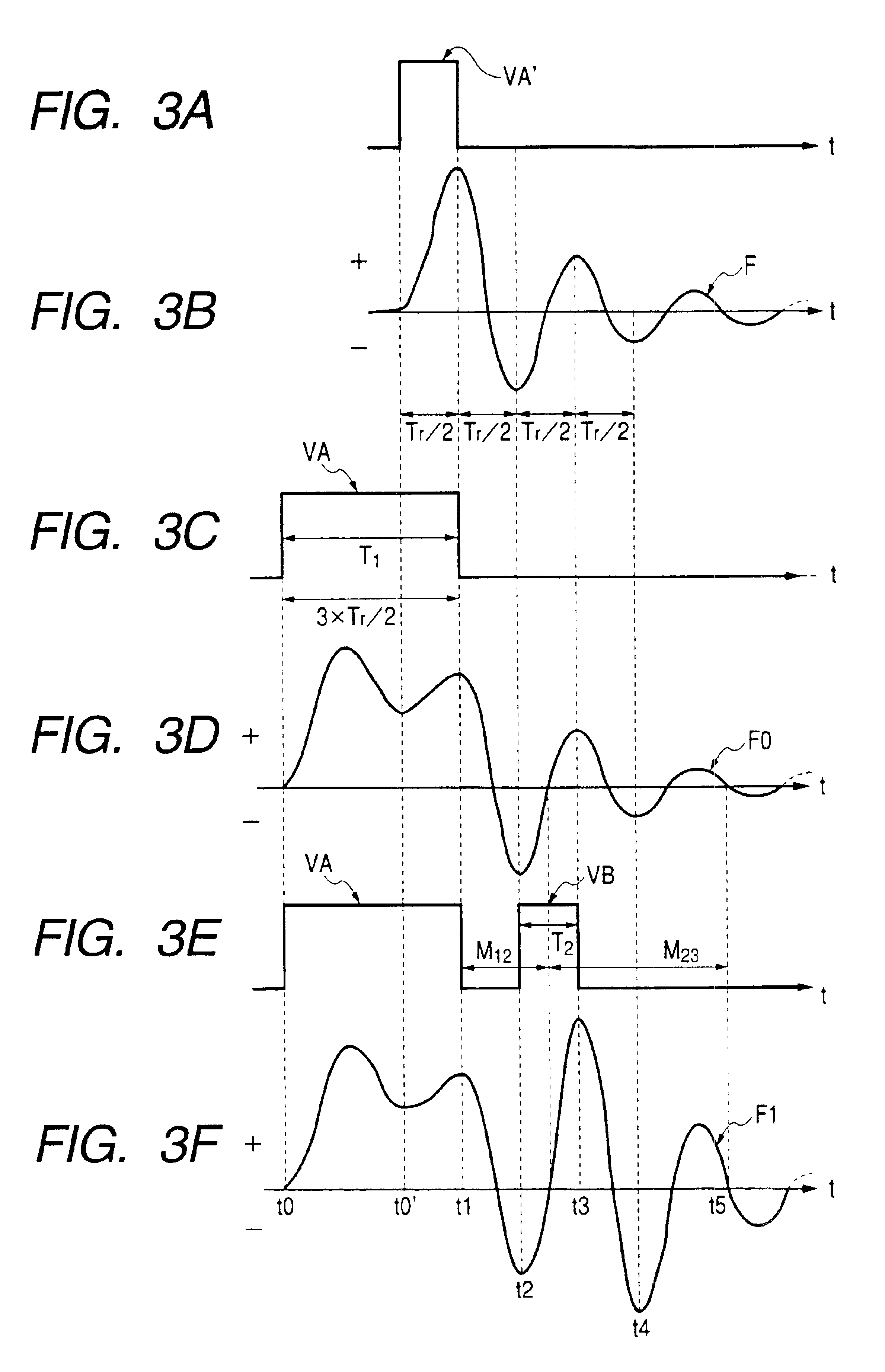
The ink used in the experiment has a viscosity of 6 mPa·s at 25° C., and a surface tension of 50 mN / m. The hydrodynamic resonant frequency of an association system of ink and a pressure-applying portion in the ink flow path was measured using an impedance measurement device, and an inverse thereof Tr=20 μsec was determined.
A liquid-receiving member is placed on a substrate stage, and the distance between the surface of the liquid-receiving member and the surface of the orifice plate of the head was set to 300 μm.
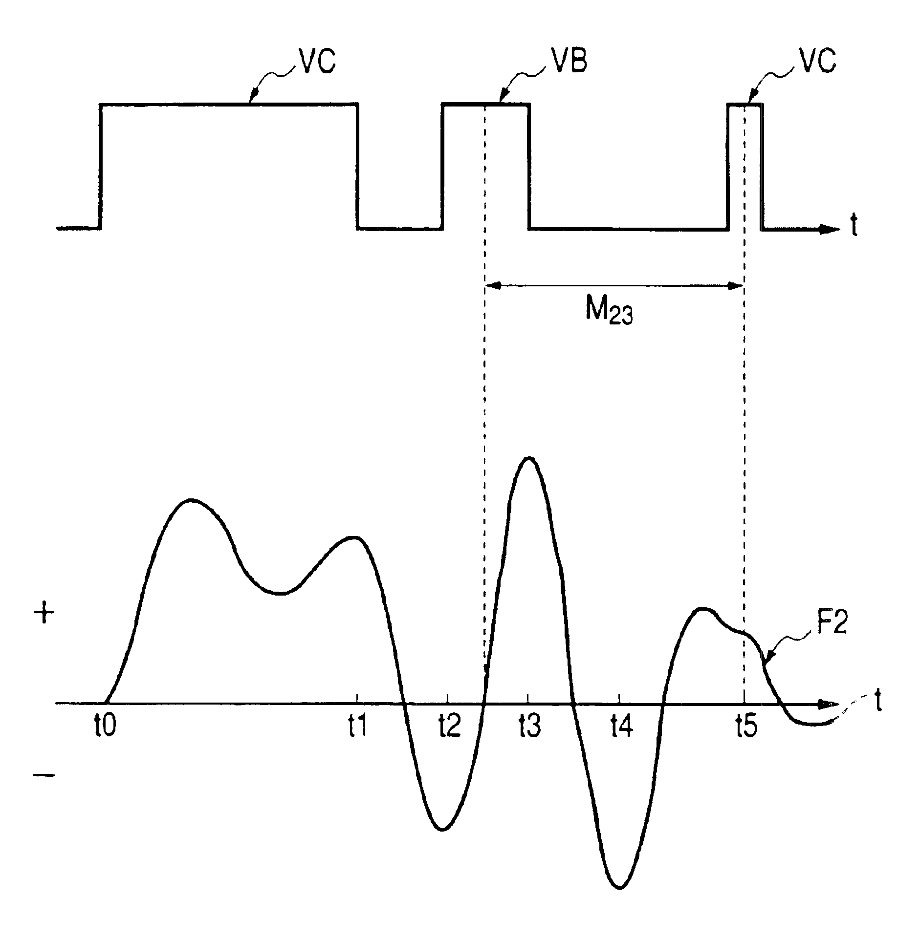
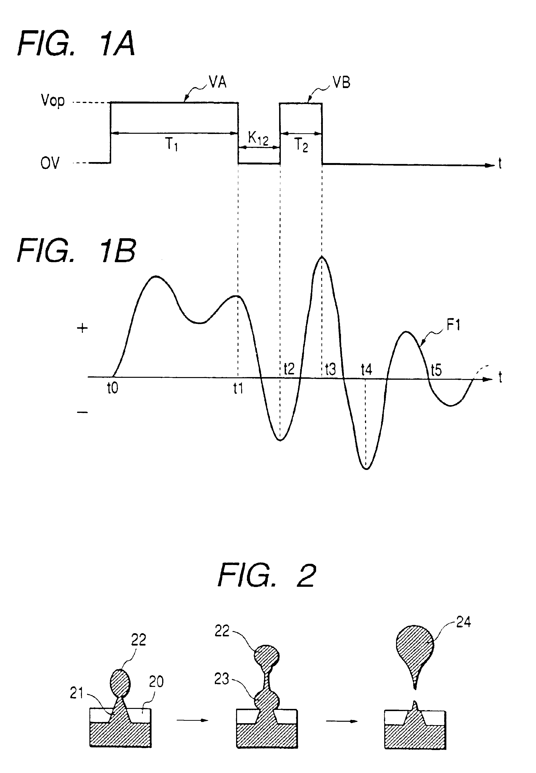
The driving waveform shown in FIG. 8 was applied to the electrodes 513 beside the air chambers 508. The driving waveform is the same a...
example 2
The head group was driven in a similar manner as that in Example 1 to perform an emission test. The result is now described in conjunction with Table 1. Table 1 indicates the result when the first emission pulse A and the second emission pulse B in the driving waveform shown in FIG. 8 are applied, and the pulse width of the emission pulse A is taken as a parameter. The ink used herein has a viscosity of 6 mPa·s at 25° C., and a surface tension of 50 mN / m, and is relatively high viscosity liquid in view of ink viscosity.
TABLE 1Speed of main dropEmissionformed by combiningAccuracy ofT1 (μs)quantitydropletsarriving point24205.8x25236.6Δ26256.9Δ2727.57∘28297.5∘2929.57.8∘30308∘3129.57.9∘32297.6∘33287.1∘34266.5Δ3524.56.3Δ36226xNote: ∘ denotes EXCELLENT; Δ denotes GOOD; and x denotes BAD.
Table 1 indicates the total amount of discharge of two ink droplets ejected in response to the emission pulses A and B with a driving voltage of 24 V. Table 1 further indicates the discharge speed and dep...
example 3
In a similar manner as that in Example 2, the pulse width of the emission pulse B was used as a variable parameter to perform a similar evaluation.
T1=30 μs was used as another parameter, and others are the same as those in Example 2.
In Example 3, it was found that the pulse width T2 when a satisfactory result was obtained is within 9 μs≦T2≦11 μs.
PUM
 Abstract
Description
Claims
Application Information
 - R&D
- Intellectual Property
- Life Sciences
- Materials
- Tech Scout
- Unparalleled Data Quality
- Higher Quality Content
- 60% Fewer Hallucinations
Browse by: Latest US Patents, China's latest patents, Technical Efficacy Thesaurus, Application Domain, Technology Topic, Popular Technical Reports.
© 2025 PatSnap. All rights reserved.Legal|Privacy policy|Modern Slavery Act Transparency Statement|Sitemap|About US| Contact US: help@patsnap.com


