Apparatus and method for in situ burning of oil spills

Inactive Publication Date: 2005-02-08
BOARD OF SUPERVISORS OF LOUISIANA STATE UNIV & AGRI & MECHANICAL COLLEGE
View PDF16 Cites 14 Cited by
  • Summary
  • Abstract
  • Description
  • Claims
  • Application Information

AI Technical Summary

Benefits of technology

The present invention provides a method for in-situ burning of oil slicks on water. The method includes the steps of: 1) providing a plurality of indivi

Problems solved by technology

Because oil is destroyed rather than collected, burning is attractive where transportation and disposal options are limited.
In addition, “boilover” may occur when underlying water layers reach boiling temperatures, quenching the burn.
This technique is costly and cumbersome to deploy, and therefore its use has been restricted to spills in remote yet assessable areas on relatively calm waters.
Dispersion rapidly thins most oil slicks to a degree that will not maintain combustion without confining booms.
Attempts to burn heavily emulsified oil have not been successful.
Evaporative losses of hydrocarbons, or weathering, results in the loss of the more easily ignited and burned volatile and semi-volatile components.
Burning of heavier oils has proven difficult.
Without the benefit of containment booms, burning can only be accomplished within the first few hours after a spill event because oil rapidly spreads to equilibrium thickness.
It is believed that no field evaluation of these materials was ever performed.
Failure to test these materials may have been the result of unfortunate timing since at the time these patents were issued, burning oil at sea was considered a problem, not a solution.
Also, because these materials were not biodegradable, they posed a potential hazard to sea life.
Additionally, recovery of these

Method used


Image

  • Apparatus and method for in situ burning of oil spills
  • Apparatus and method for in situ burning of oil spills
  • Apparatus and method for in situ burning of oil spills

Examples


experimental examples

Several criteria were used to initially assess the performance of various designs. These criteria included: (1) uptake of oil and water while floating on an oil-water interface and during burning, (2) tolerance to burning, (3) ability to maintain structural integrity and float for 7 days, and (4) efficacy in burning a 1-mm oil slick. The methods for measuring these criteria are as follows.

1. Measuring Basic Criteria.

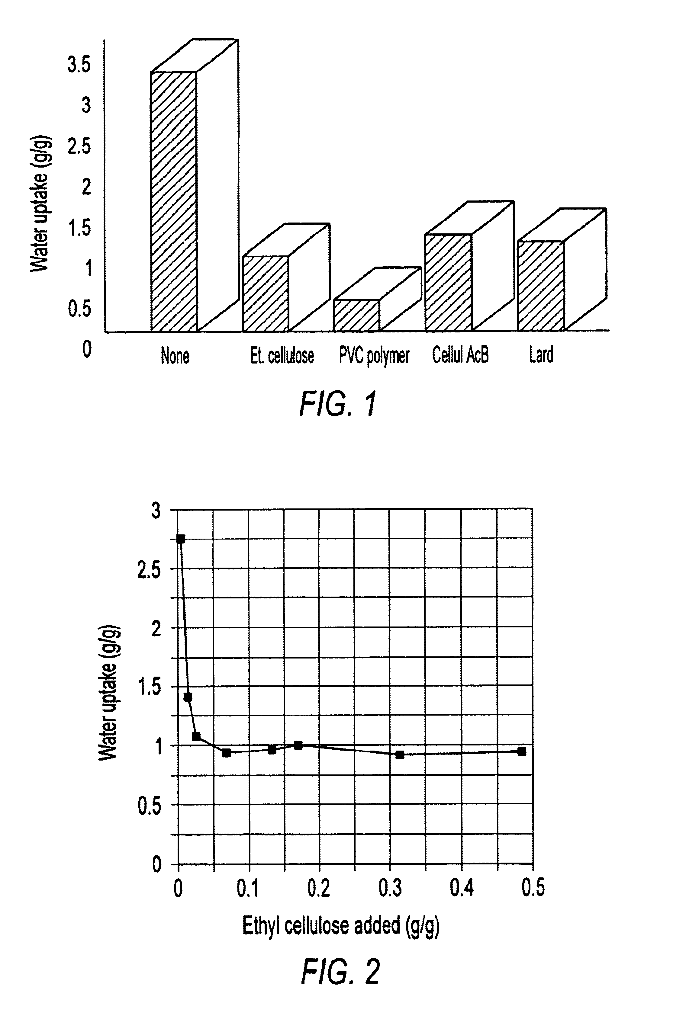
1.1 Uptake of oil and water. To measure the relative uptake of oil and water, wicks were weighted and then placed in a 600 ml beaker containing 400 ml tap water and sufficient South Louisiana Sweet crude oil or diesel fuel to provide a slick thickness of 2-mm. After 2 hours, the devices were removed, placed in tared 500 ml widemouth jars, and the weight after adsorption measured to determine uptake of both oil and water. To determine the amount of oil absorbed, a wick was then chopped into a number of pieces and mixed with 250 ml of tetracholorethylene (TCE). The jar was...


PUM


Abstract

A method for in-situ burning of oil slicks on water, including the steps of: 1) providing a plurality of individual floating wicks; 2) positioning the wicks in the oil slick; and 3) igniting the wicks. Additionally, a method for manufacturing floating wicks for use in burning oil spills, including the steps of: 1) providing a wick material having a dry density less than water; 2) applying to the wick material an oleophilic, hydrophobic coating such that the coated wick material has an oil uptake capacity of at least 2 g/g and a water uptake capacity of no greater than 5 g/g; and 3) drying the wick material.

Description

TECHNICAL FIELDThe present invention relates to methods of cleaning up oil spills on bodies of water. In particular, the present invention relates to a novel method of in situ burning of oil on bodies of water.BACKGROUND ARTIn situ burning has received considerable attention in recent years as a cleanup method for oil in both upland ecosystems and on water. In situ burning involves the ignition and burning of oil spilled on water, vegetation or soils. The use of burning to address large scale oil spills at sea dates back to the Torrey Canyon incident in 1967. The failure of that and similar efforts discouraged the use of in situ burning until interest was renewed by the successful burn during the Exxon Valdez incident in 1989. Since then laboratory tests, the Mobile AL burn tests in 1991-1994, the Alaska Emulsion Burn Experiments, and the Newfoundland Offshore Burn Experiment showed that when properly managed in situ burning is a rapid, effective and environmentally safe technology ...

Claims


Application Information

Patent Timeline
IPC IPC(8): C02F1/68E02B15/04
CPCC02F1/681E02B15/042Y10S210/924Y02A20/204
Inventor BREITENBECK, GARY A.
Owner BOARD OF SUPERVISORS OF LOUISIANA STATE UNIV & AGRI & MECHANICAL COLLEGE
Why Eureka
Try Eureka