Electron beam device and method for stereoscopic measurements

a stereoscopic measurement and beam technology, applied in the direction of instruments, material analysis using wave/particle radiation, nuclear engineering, etc., can solve the problem of insufficient control accuracy and achieve the effect of high accuracy

Inactive Publication Date: 2005-02-08
KK TOPCON
View PDF13 Cites 38 Cited by
  • Summary
  • Abstract
  • Description
  • Claims
  • Application Information

AI Technical Summary

Benefits of technology

This invention has been made to solve the above problems. The first object of this invention is to provide an electron beam device that makes it possible to appropriately process three-dimensional detection data obtained with an electron microscope, to view specimen images three-dimensionally with high accuracy, and to carry out measurement of three-dimensional shapes on the basis of the accurate three-dimensional viewing.
Preferably the reference marks serving as reference points are at least three points of contamination or defects to produce rectified images. If preparation of the reference mark is judged to have been completed when the signal of an electron beam detected with the electron beam detecting section 4 reaches a predetermined level, the ending time of the reference mark preparation is known objectively and the shapes of the reference points become uniform. If the diameter of the electron beam for preparing the reference marks is made different from the diameter of the electron beam for detecting the image of the specimen 9 with the electron beam device 10, image recognition of the reference mark can be carried out smoothly. If the density of the electron beam for preparing reference marks is controlled to be greater than that of the electron beam while being moved over the reference template substrate 40b, formation of the reference mark is carried out with less deformation of the reference surface of the reference template substrate 40b associated with the formation of the reference mark.

Problems solved by technology

In conventional methods, however, there is a problem that the angular control is done generally in the order of a few degrees or a few minutes and therefore the control accuracy is insufficient for, performing accurate measurement of three-dimensional shapes by the stereovision of the right and left images.

Method used


Image

  • Electron beam device and method for stereoscopic measurements
  • Electron beam device and method for stereoscopic measurements
  • Electron beam device and method for stereoscopic measurements

Examples


first embodiment

2. First Embodiment

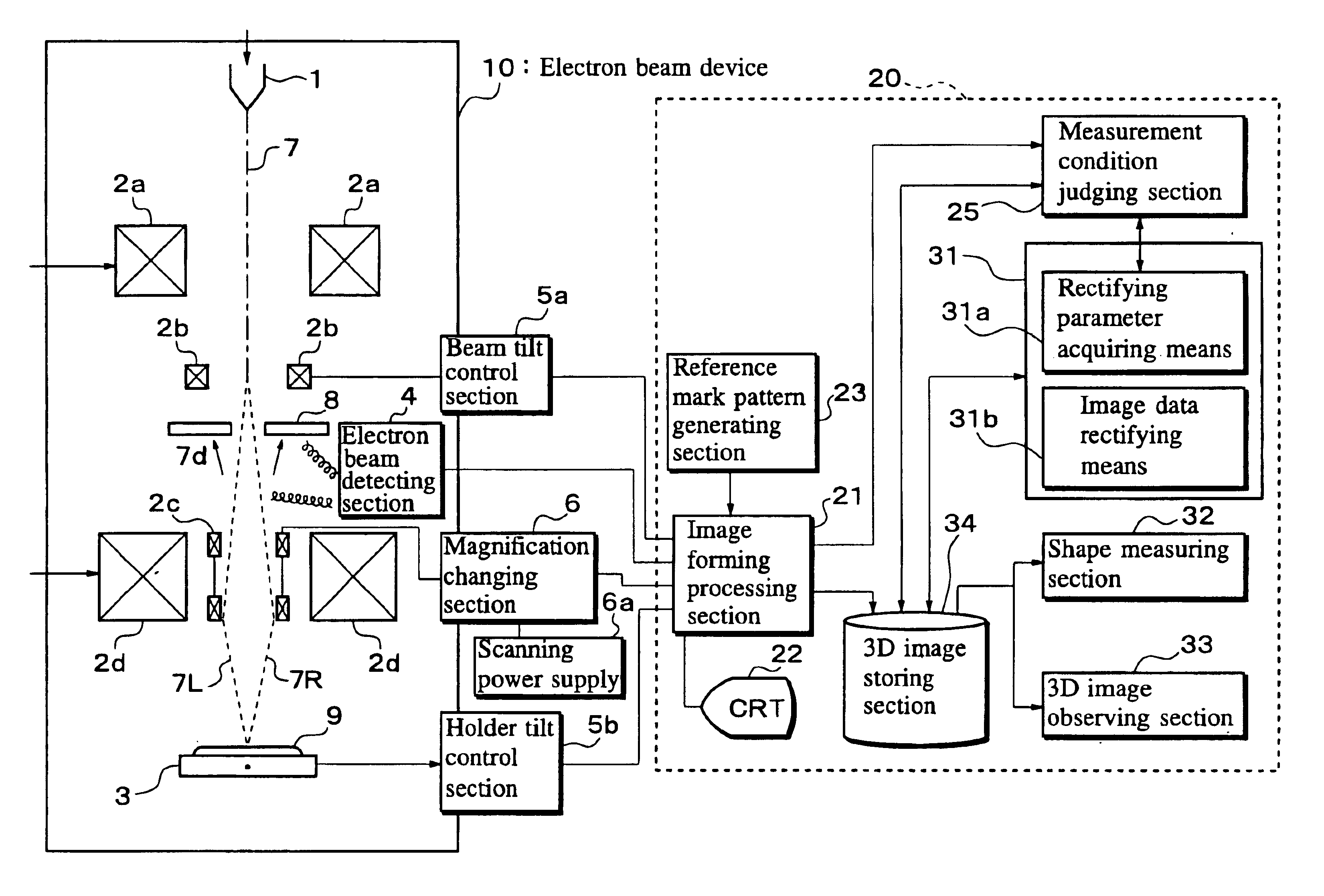
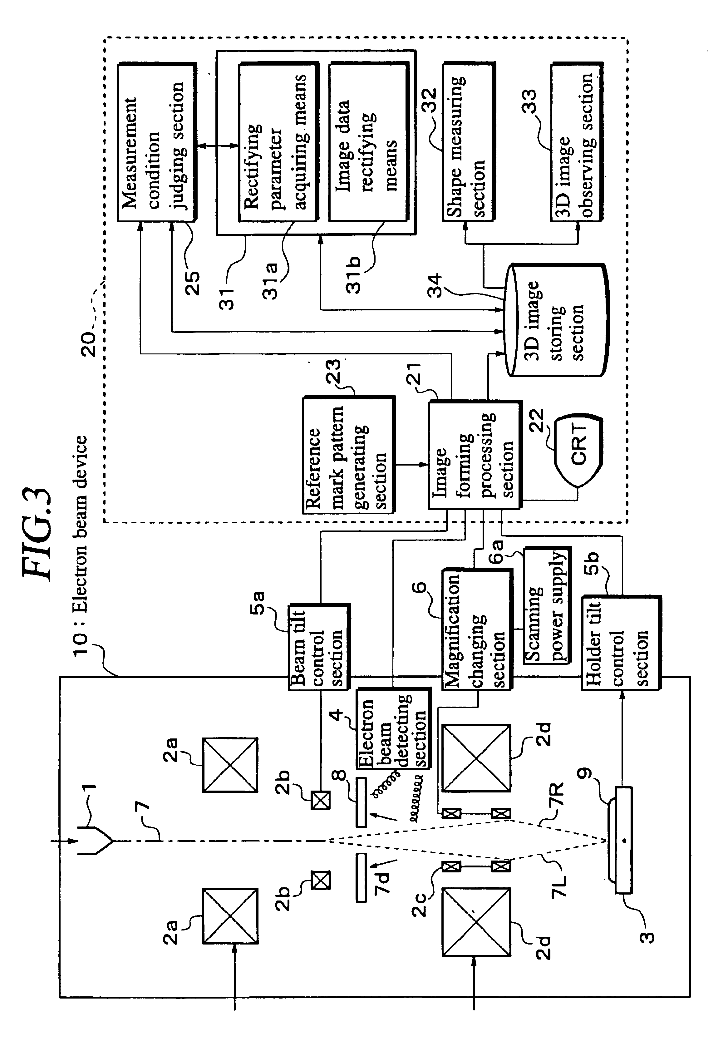
The first embodiment will be described in reference to appended drawings. FIG. 3 is a block diagram of the first embodiment of this invention, in which a three-dimensional image is produced by deflecting the electron beam of a scanning electron microscope. As shown, a scanning electron microscope or an electron beam device 10 comprises an electron beam source 1 for emitting an electron beam 7, an electron optical system 2 for irradiating the electron beam 7 onto a specimen 9, a specimen holder 3 capable of holding the specimen 9 at different tilt angles, a magnification changing section 6 for changing the magnifying power of the electron optical system 2, a scanning power supply 6a for supplying electric power to the magnification changing section 6, a detector 4 for detecting the electron beam 7, a tilt control section 5 or a beam tilt control section 5a for controlling the tilt of the electron beam 7, and a secondary electron converting target 8 for attenuating ...

second embodiment

3. Second Embodiment

FIG. 15 is a block diagram of the second embodiment of this invention in the case of taking three-dimensional images with a scanning electron microscope with the specimen holder at different tilt angles. In the second embodiment, the holder tilt control section 5b is used as the tilt control section 5 for the specimen holder 3 and the beam tilt angle control section 5a is not operated. Here, two relative tilt angles are produced between the specimen holder 3 and the electron beam 7 with the holder tilt control section 5b. One relative tilt angle is produced when the right edge of the specimen bolder 3 is raised as shown with the symbol R and the other relative tilt angle is produced when the specimen holder 3 is tilted with its left edge raised as shown with the symbol L. While the number of tilt angles is not limited to two but may be any plural number, two is a minimum for obtaining images for stereovision. Taking images with the detector 4 at specified angles ...

third embodiment

4. Third Embodiment

FIG. 16 is a block diagram of the third embodiment of this invention in the case of taking three-dimensional images with a transmission electron microscope with the specimen holder set to different tilt angles. Since the electron beam device 10 is a transmission electron microscope, the electron beam detecting sections 4a and 4b are located opposite to the electron beam source 1 beyond the specimen holder 3. The electron optical system 2 is made up of a first electron optical system and a second electron optical system that directs the electron beam 7 passing through the specimen 9 to the detector 4a, such as a CCD (charge-coupled device). As the first electron optical system, a condenser lens 2a is provided to change the electron flow density, divergent angle, and irradiation area of the electron beam 7 emitted from the electron beam source 1. As the second electron optical system, there are provided an objective lens 2g in the first stage of the focusing system,...


PUM

PropertyMeasurementUnit
tilt angleaaaaaaaaaa
relative tilt angleaaaaaaaaaa

Abstract

An electron beam device according to the present invention is made up of an electron beam source for emitting an electron beam, an electron optical system for irradiating the electron beam onto a specimen, a specimen holder for holding the specimen, a specimen tilting section for producing relative tilt angles between the specimen holder and the electron beam, an electron beam detecting section for detecting electron beam emitted from the specimen, and a data correcting section for correcting the three-dimensional detection data to have specified relationship under the condition of a relative tilt angle between the specimen holder and the electron beam.

Description

BACKGROUND OF THE INVENTION1. Field of the InventionThis invention relates to an electron beam device, a data processor for the electron beam device, and a method of producing stereo data of the electron beam device, for converting images obtained with an electron microscope into images for stereovision and for finding shapes of specimens. This invention also relates to a reference template and the preparation thereof for use in obtaining parameters necessary for correcting deviation of three-dimensional images obtained with the electron microscope and necessary for correcting lens distortion.2. Description of the Related ArtFor three-dimensional viewing of a specimen with a transmission electron microscope (TEM), the specimen is tilted to obtain right and left transmission images at different tilt angles, and right and left images are used for stereovision. In the case of the stereovision with a scanning electron microscope (SEM), either the beam of electrons or the specimen is til...

Claims


Application Information

Patent Timeline
Patent Type & Authority Patents(United States)
IPC IPC(8): H01J37/26
CPCH01J37/26H01J2237/2611
Inventor KOCHI, NOBUOKOIKE, HIROTAMI
Owner KK TOPCON
Why Eureka
Try Eureka