LED retrofit lamp

a retrofit lamp and led technology, applied in the field of lamps, can solve the problems of inability to directly connect fluorescent lamps to alternating current power lines, overheating and eventually destroying themselves, and additive approaches that do not reduce or eliminate the amount of hazardous mercury in the environment, so as to achieve softer and warmer light output, improve the effect of thermal performance and lightening and more superior thermal performan

Inactive Publication Date: 2005-02-08
SIGNIFY HLDG BV
View PDF12 Cites 457 Cited by
  • Summary
  • Abstract
  • Description
  • Claims
  • Application Information

AI Technical Summary

Benefits of technology

It can be appreciated by someone skilled in the art to use a lesser amount of LEDs in the circuit board configurations to project light from an existing fluorescent fixture in the general direction out of the fixture only without any light projected back into the fixture itself. This will allow for lower power consumption, material costs, and will offer greater fixture efficiencies with reduced light losses.
More recently, Lumileds Lighting, LLC now offers a Luxeon warm white LED with a 90 CRI (Color Rendering Index) and 3200 degrees Kelvin CCT (Correlated Color Temperature). Lumileds Luxeon warm white is the first generally available low CCT and high CRI warm white solid-state light source. This new Luxeon LED opens the door for significantly greater use of solid-state illumination in interior and task lighting applications by replicating the soothing, warm feel typically associated with incandescent and halogen lamps. The additional benefit here being the availability of true LED retrofit lamps for existing and new fluorescent lamp fixtures that offer a softer and warmer light output similar to the output produced by incandescent and halogen lamps. An alternate arrangement to get similar CRI and CCT would be to use existing high CCT white color LEDs with a combination of yellow or amber color LEDs to achieve the desired color tone. This lower CCT break through was never available before to the end user with conventional fluorescent lamps unless they used a color film wrap or similar product to “color” the fluorescent lamp light output.

Problems solved by technology

Unlike incandescent lamps, fluorescent lamps cannot be directly connected to alternating current power lines.
Unless the flow of current is somehow stabilized, more and more current will flow through the lamp until it overheats and eventually destroys itself.
Unfortunately, the additive approach does not reduce or eliminate the amount of hazardous mercury in the environment.
More importantly, the additives may not work as effectively in the real world as they do in the laboratory TCLP test.
Therefore, the additives that become available during the TCLP test to reduce mercury leaching may not or only partly, do their job in real world disposal.
As a consequence, lamps that rely on additives pass TCLP, but may still have relatively high amounts of mercury leaching out into the environment.
However, the “additive” approach is not a guarantee that only small amounts of mercury will leach into the environment upon disposal.
They have indicated that if lamps with additives were thrown away as non-hazardous waste and are later found to behave differently in the landfill, then the generators and those who dispose of such lamps could potentially face the possibility of having violated the hazardous waste disposal regulation known as RCRA.
Besides the emission of ultra-violet (UV) rays and the described use of mercury in the manufacture of fluorescent lamps, there are other disadvantages to existing conventional fluorescent lamps that include flickering and limited usage in cold weather environments.
No mercury lamps are the best option for the environment and for the end-user that desires non-hazardous lamps.
LED lamps consume less energy than conventional lamps and give much longer lamp life.
Unfortunately, the prior art LED lamp designs used thus far still do not provide sufficiently bright and uniform illumination for general lighting applications, nor can they be used strictly as direct and simple LED retrofit lamps for existing fluorescent lighting fixtures and ballast configurations.
But as mentioned before, none of the disclosed retrofit lamps are designed for use as a retrofit lamp for a fluorescent lighting fixture using the existing fluorescent sockets and ballast electronics.
This configuration has its limitation, because the light output is not evenly distributed away from the center.
In addition, the disclosed configuration of the LEDs limits its use in non-linear and curved housings.
Again, power to the LEDs is provided on one end of the lamp only and cannot be used in either non-linear or curved housings.

Method used


Image

  • LED retrofit lamp
  • LED retrofit lamp
  • LED retrofit lamp

Examples


Embodiment Construction

Reference is now made to the drawings and in particular to FIGS. 1-10 in which identical of similar parts are designated by the same reference numerals throughout.

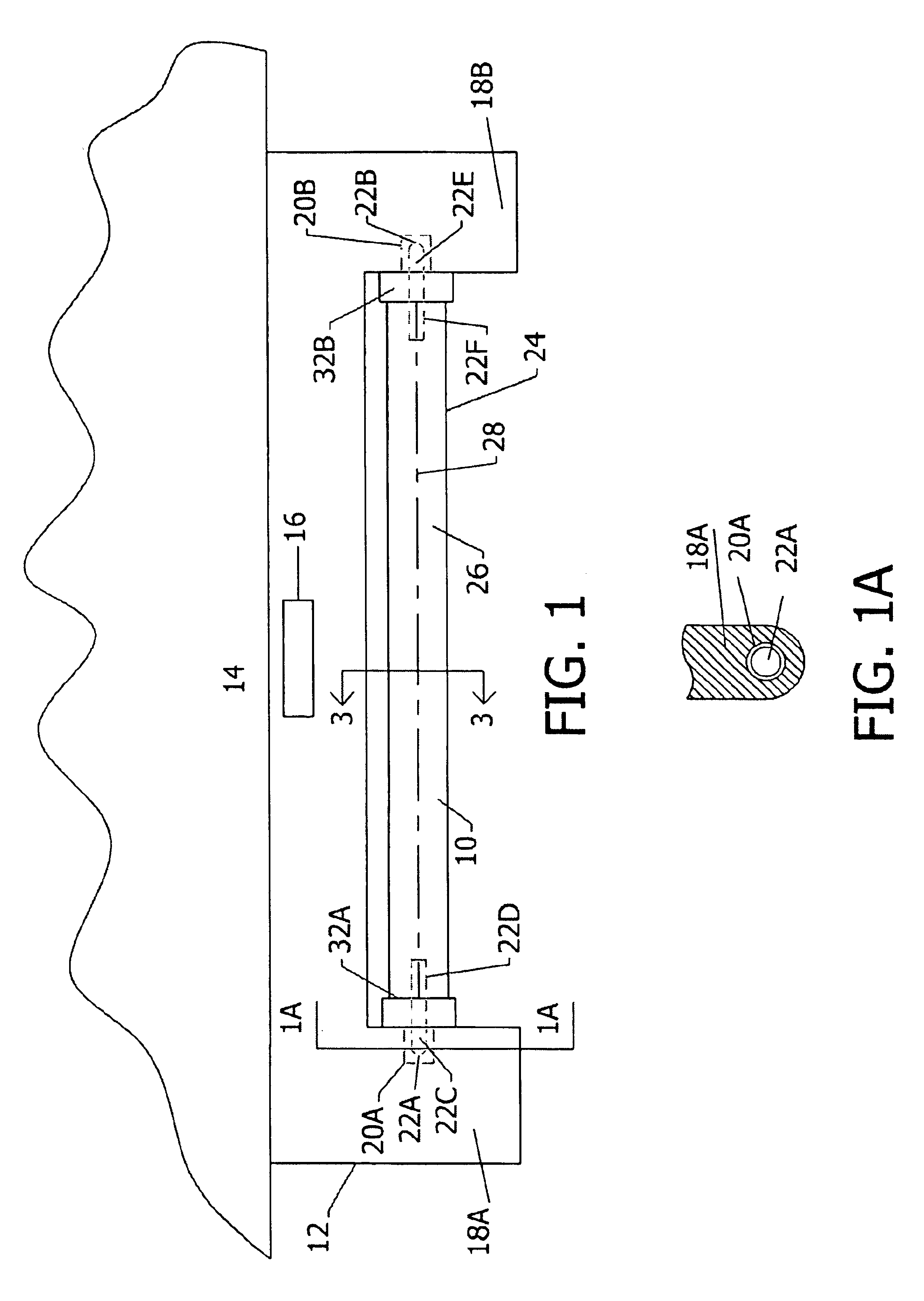
An LED lamp 10 shown in FIGS. 1-10 is seen in FIG. 1 retrofitted to an existing elongated fluorescent fixture 12 mounted to a ceiling 14. An instant start type ballast assembly 16 is positioned within the upper portion of fixture 12. Fixture 12 further includes a pair of fixture mounting portions 18A and 18B extending downwardly from the ends of fixture 12 that include ballast electrical contacts shown as ballast end sockets 20A and 20B that are in electrical contact with ballast assembly 16. Fixture sockets 20A and 20B are each single contact sockets in accordance with the electrical operational requirement of an instant start type ballast. As also seen in FIG. 1A, LED lamp 10 includes opposed single-pin electrical contacts 22A and 22B that are positioned in ballast sockets 20A and 20B, respectively, so that LED lamp 10 i...


PUM


Abstract

An LED lamp for mounting to an existing fluorescent lamp fixture having a ballast assembly including ballast opposed electrical contacts, comprising a tubular wall generally circular in cross-section and having tubular wall ends with one or more LEDs positioned within the tubular wall between the tubular wall ends. An electrical circuit provides electrical power from the ballast assembly to the LED(s). The electrical circuit includes at least one metal substrate circuit board and means for electrically connecting the electrical circuit with the ballast assembly. The electrical circuit includes an LED electrical circuit including opposed electrical contacts. Each metal substrate circuit board supports and holds the one or more LEDs and the LED electrical circuit. Each metal substrate circuit board is positioned within the tubular wall between the tubular wall ends. At least one electrical string is positioned within the tubular wall and generally extends between the tubular wall ends. One or more LEDs are in electrical connection with at least one electrical string and are positioned to emit light through the tubular wall. Means for suppressing ballast voltage is included. The metal substrate circuit board includes opposed means for connecting the metal substrate circuit board to the tubular wall ends, which include means for mounting the means for connecting, and the one or more metal substrate circuit boards.

Description

FIELD OF THE INVENTIONThe present invention relates to lamps with light emitting diodes mounted in tubular housings.BACKGROUND OF THE INVENTIONWith the present energy crisis, it becomes evident that the need for more energy efficient lamps of all configurations need to be developed and implemented as soon as possible for energy conservation.Many private, public, commercial and office buildings including transportation vehicles like trains and buses, use fluorescent lamps installed in lighting fixtures. Fluorescent lamps are presently much more efficient than incandescent lamps in using energy to create light. Rather than applying current to a wire filament to produce light, fluorescent lamps rely upon an electrical arc passing between two electrodes, one located at either ends of the lamp. The arc is conducted by mixing vaporized mercury with purified gases, mainly Neon and Krypton or Argon gas inside a tube lined with phosphor. The mercury vapor arc generates ultraviolet energy, wh...

Claims


Application Information

Patent Timeline
Patent Type & Authority Patents(United States)
IPC IPC(8): F21K7/00F21K99/00H05B44/00
CPCH05B33/0809F21K9/17H05B33/0803F21Y2101/02F21Y2103/003F21Y2103/025Y10S362/80Y02B20/386F21K9/27F21Y2103/10F21Y2115/10F21Y2103/37F21K9/278Y02B20/30H05B45/3578
Inventor LEONG, SUSAN J.KIT, JOHN
Owner SIGNIFY HLDG BV
Why Eureka
Try Eureka