Wearable communication system

a communication system and wearable technology, applied in the field of wearable communication systems, can solve the problems of cumbersome operation of bar code readers, large size, and use of both hands, and achieve the effect of better ergonomic allocation of wearable devices

Inactive Publication Date: 2005-02-08
SYMBOL TECH INC
View PDF65 Cites 217 Cited by
  • Summary
  • Abstract
  • Description
  • Claims
  • Application Information

AI Technical Summary

Benefits of technology

The keyboard permits single handed operation in the pocket (by placing the hand in the same pocket); but the keyboard can be removed, held in one hand and operated by the other hand. The keyboard contains a limited key set, however, the keyboard is programmable or trainable for specific operations and allows “chord”-ing of key activations to increase the functionality of the limited key set.
A bar code scanner, a wrist unit and a CPU unit can be distributed on an operator's body in such a way as to minimize fatigue and to enhance ergonomic usefulness of the overall system. In addition to the three components listed above, the system may also include additional peripheral components, such as a printer, a magnetic-stripe reader, heads-up display, tactile gauge-sensor or any other needed devices. The individual components communicate with each other using a wireless communication channel, preferably a short range communication channel. This wireless connectivity can be achieved via a short range local network, often called a Personal Area Network (PAN). The communication channel can be, but is not limited to, a radio frequency (RF), an infra-red (IR), or an acoustic communication channel. Thus, communication with the bar code scanner is established via a bi-directional or a uni-directional wireless link. In case this link is bi-directional, the bar code scanner includes a transmitter and a receiver. In case this link is uni-directional, the bar code scanner includes only a transmitter. In certain configurations, the wrist unit and the CPU unit may be combined into a single unit called a controller. The components distributed on an operator's body form a network called a Personal Area System (PAS). The PAS components communicate over a Personal Area Network (PAN).
The invention also contemplates a miniature voice over IP (Internet Protocol) communication module capable of being designed into a headset unit having a speaker and a microphone. Alternatively, the module can be designed to be carried on other parts of the user's body for better ergonomic allocation of the user worn devices. The module is connected to another system component located either on the user's body, or a server located on a network, for voice recognition of user's commands. Thus, by providing voice recognition capabilities to a voice-over-IP communication module, the system allows for virtually hands free operation of the phone module for communication purposes.

Problems solved by technology

Such units incorporating so many different elements, however, tend to be larger than many dedicated bar code readers and cumbersome to operate as bar code readers, particularly for extended periods.
Also, conventional integrated devices often require the operator to hold the device in one hand and operate the keyboard with the other.
Such operation requires use of both hands and does not allow the user to perform other manual tasks at the same time.
These problems, together with problems related to securing and carrying the integrated terminals when not in use, tend to discourage employees from using the data input system, thereby defeating the purpose of the system and particularly the advantages otherwise associated with bar code data entry.
Similar problems exist in other types of portable computer or data devices.

Method used


Image

  • Wearable communication system
  • Wearable communication system
  • Wearable communication system

Examples


Embodiment Construction

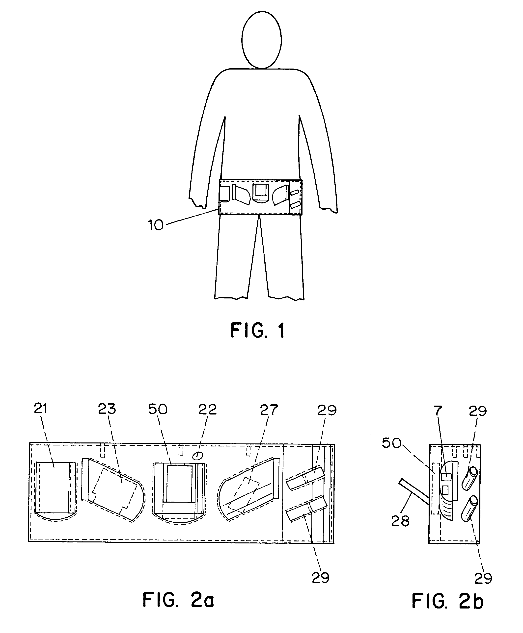
A portable data system includes a work or utility harness such as a tool belt, which is worn by the system operator. Usually the harness is worn on the upper portion of the body for easy access. In the example illustrated in FIG. 1, the harness is in the form of a large belt, similar to that used for holding tools or other equipment. Harness 10 contains a number of pockets or other fittings suitable for holding system components. However, the harness is not limited to a belt with pockets, and can include vertical shoulder straps (not shown) and a horizontal chest strap (not shown). While the harness is shown with pockets, other structures can be included to hold the system components, for example, large pouches, straps or rings. Whereas tool belts and other such utility harnesses are normally made of leather, the harness of the present invention can be made of any suitable material such as grip-stop nylon.

As shown in FIG. 2A, the belt has, for example, six pockets which serve as sup...


PUM


Abstract

A portable data input or computer system includes an input / output device such as a keyboard and a display, another data input device such as an optical bar code scanner, and a data processor module. To scan bar code type indicia, the operator points the scanner at the bar code and triggers the scanner to read the indicia. All the system components are distributed on an operator's body and together form a personal area system (PAS). Components may include a scanner or imager, a wrist unit, a headpiece including an eyepiece display, speaker and a microphone. Components within a particular PAS communicate with each other over a personal area network (PAN). Individual PASs may be combined into a network of PASs called a PAS cluster. PASs in a particular PAS cluster can communicate with each other over another wireless communication channel. Individual PAS can gain access to a Local Area Network (LAN) and / or a Wide Area Network (WAN) via an access point. Individual PASs can use devices, such as servers and PCs situated either on the LAN or the WAN to retrieve and exchange information. Individual PAS components can provide automatic speech and image recognition. PAS components may also act a telephone, a pager, or any other communication device having access to a LAN or a WAN. Transmission of digitized voice and / or video data can be achieved over an Internet link.

Description

TECHNICAL FIELDThe present invention relates to a portable computer or data input system, typically including an optical scanner, or imager, wherein the system is incorporated into a special utility harness resembling a tool belt or the like worn by the system operator. The present invention also relates to a portable data communication system, typically including an optical scanner, or imager, wherein the system is distributed on an operators body and wherein system components communicate with each other over a wireless communication network. The present invention also relates to a portable data communication system, typically including an optical scanner, or imager, being distributed on an operator's body and capable of communicating with other devices over a Local Area Network or / and a Wide Area Network.BACKGROUND ARTOptical readers, such as bar code readers, are now common. Typically, a bar code comprises a series of encoded symbols, and each symbol consists of a series of light...

Claims


Application Information

Patent Timeline
Patent Type & Authority Patents(United States)
IPC IPC(8): G06F1/16
CPCG06F1/163G06F1/1698G06F1/1684G06F1/1662
Inventor SWARTZ, JEROMESLUTSKY, MICHAELBARD, SIMONSHELLHAMMER, STEPHEN J.CONNELLY, JAMESHETFIELD, MARGARET L.SHARONY, JACOBRAMPUTI, MICHAEL A.POLONIEWICZ, PAUL R.KATZ, JOSEPHBEACH, ROBERT E.
Owner SYMBOL TECH INC
Why Eureka
Try Eureka