Polarized display with wide-angle illumination
Inactive Publication Date: 2005-02-08
BURRIS MICHELE M
View PDF7 Cites 32 Cited by
- Summary
- Abstract
- Description
- Claims
- Application Information
AI Technical Summary
Benefits of technology
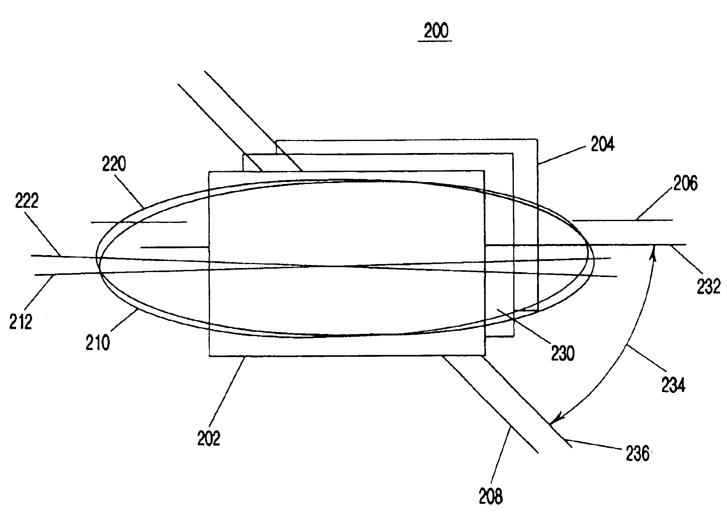
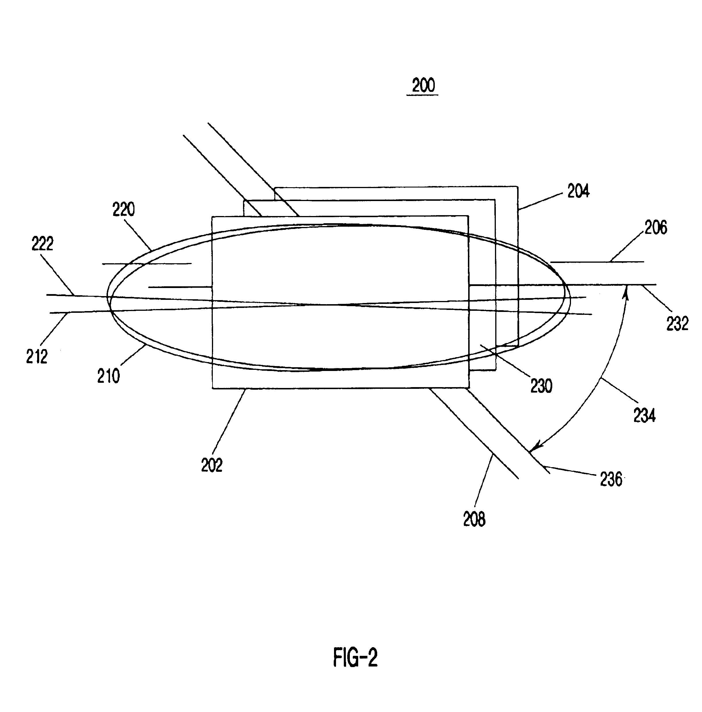
[0022]The present invention overcomes the difficulties described above by introducing a polarization rotation element between the display and the rear element(s) in the display to rotate the plane of polarized light transmitted from the rear optical elements to the rear polarizer. The polarization rotation element can take any of many forms. The choice of which particular element to use will depend upon the details and demands of a particular application. Factors to be considered might include, for example, dispersion, tolerance of chromaticity shifts, efficiency and cost. Through the use of the present invention, the plane in which the angle of sufficient off normal brightness is broadest can be reoriented to a plane that is most ideal for the particular application, thus dramatically improving the overall performance and efficiency of such displays.
[0023]The present invention described herein offers a significant advantage in display transmittance for wide viewing angles, and dramatically increases the compatibility of optical elements such as pre-polarizers with wide-viewing angle polarized displays.
Problems solved by technology
Many of these optical films remain inadequate, however, for significantly improving the off normal brightness at the wider angles required for many applications.
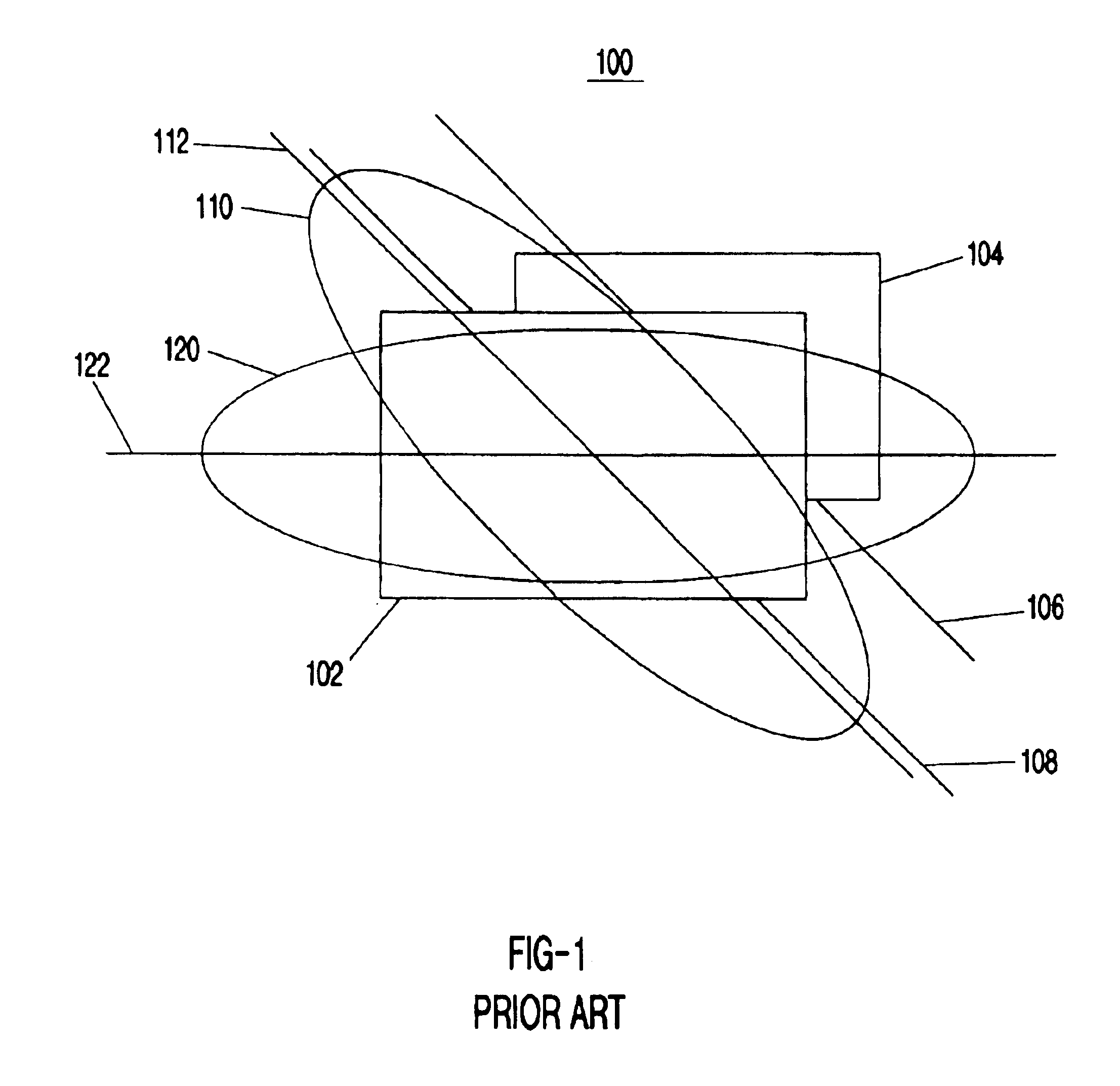
The prior attempts to have optimized illumination for wide angle polarized displays have suffered from a number of drawbacks and limitations.
Method used
View moreImage
Smart ImageViewing Examples
Examples
second embodiment
[0028]FIG. 3 depicts a polarized display device incorporating the present invention.
third embodiment
[0029]FIG. 4 depicts a polarized display device incorporating the present invention.
fourth embodiment
[0030]FIG. 5 depicts a polarized display device incorporating the present invention.
[0031]FIG. 6 depicts one embodiment of a polarization rotation element according to the present invention.
Login to View More PUM
 Abstract
An apparatus and method for improving the brightness of a polarized display at viewing angles off of the vector normal to the display panel. The advantages of the present invention will be most pronounced when employed in applications in which the viewing angle requirements are asymmetric, such as for avionics applications that require cross-cockpit viewability of the display. The present invention overcomes the limitations inherent in earlier designs by introducing a polarization rotation element as part of the display device to rotate the polarization of light from one orientation to another orientation. Through the use of the present invention, the axis in which the angle of sufficient off normal brightness is broadest can be reoriented to an axis that is most ideal for the particular application, thus dramatically improving the overall performance and efficiency of such displays.
Description
RELATED APPLICATION[0002]This application claims priority of U.S. Provisional Application Ser. No. 60 / 197,705 entitled “Polarized display with wide-angle illumination,” filed on Apr. 18, 2000, the teachings of which are incorporated herein by reference.FIELD OF THE INVENTION[0003]The present invention relates generally to the field of polarized displays, including, without limitation, liquid crystal displays, ferroelectric displays, projection displays and other similar illuminated display devices and systems. More specifically, the present invention relates generally to polarized displays requiring illumination and viewability across a wide range of viewing angles. The present invention is directed to methods and apparatuses for maximizing the light transmittance of a polarized display in the case where this wide angle illumination is desired.BACKGROUND OF THE INVENTION[0004]Polarized displays, especially those making use of the unique properties of liquid crystalline materials, ar...
Claims
Login to View More Application Information
Patent Timeline
 IPC IPC(8): G02F1/1335G02B5/30G02F1/13G02B27/28G02F1/13357G02F1/13363
CPCG02B5/3016G02B5/3083G02F1/13363G02F2413/08G02F2001/133638G02F2413/02G02F1/133638G02F1/1335
Inventor LARSON, BRENT D.
Owner BURRIS MICHELE M
Features
- R&D
- Intellectual Property
- Life Sciences
- Materials
- Tech Scout
- Unparalleled Data Quality
- Higher Quality Content
- 60% Fewer Hallucinations
Learn More Browse by: Latest US Patents, China's latest patents, Technical Efficacy Thesaurus, Application Domain, Technology Topic, Popular Technical Reports.
© 2025 PatSnap. All rights reserved.Legal|Privacy policy|Modern Slavery Act Transparency Statement|Sitemap|About US| Contact US: help@patsnap.com


