

Capacitors with recessed rivets allow smaller implantable defibrillators
a defibrillator and capacitor technology, applied in the field of capacitors, can solve the problems of omitting or skipping even one manufacturing step, reducing increasing assembly time and cost, so as to reduce the need, reduce the thickness of the foil, and increase the capacitor height
- Summary
- Abstract
- Description
- Claims
- Application Information
AI Technical Summary
Benefits of technology
Problems solved by technology
Method used
Image

Examples
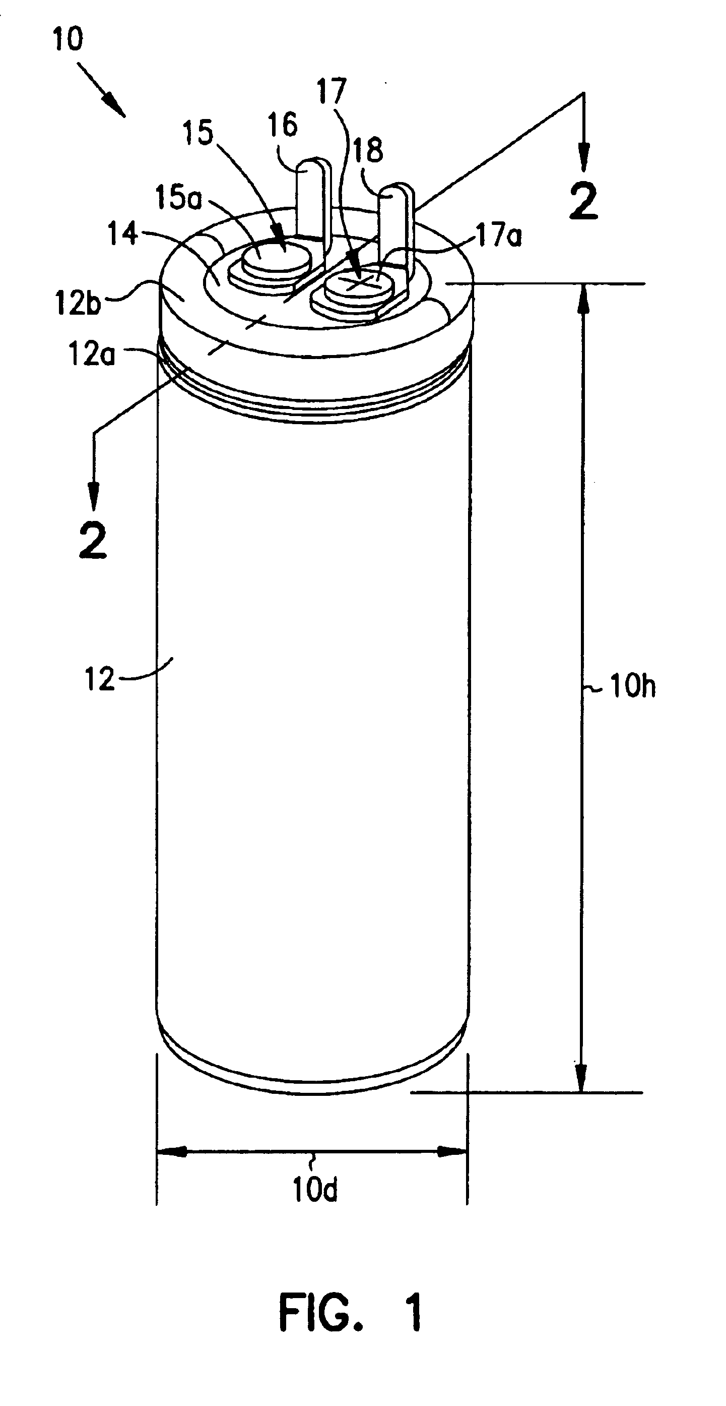
case 12
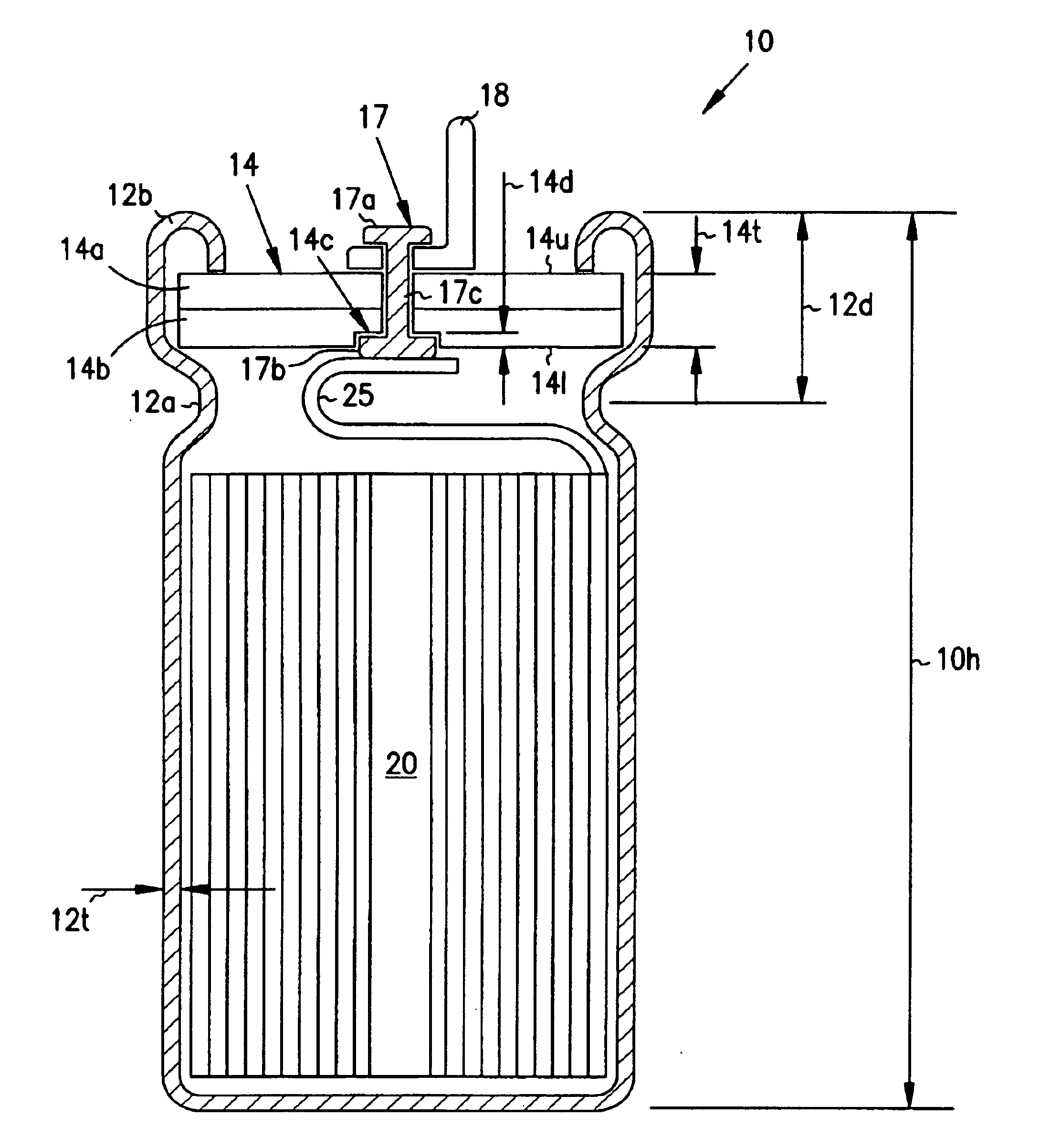
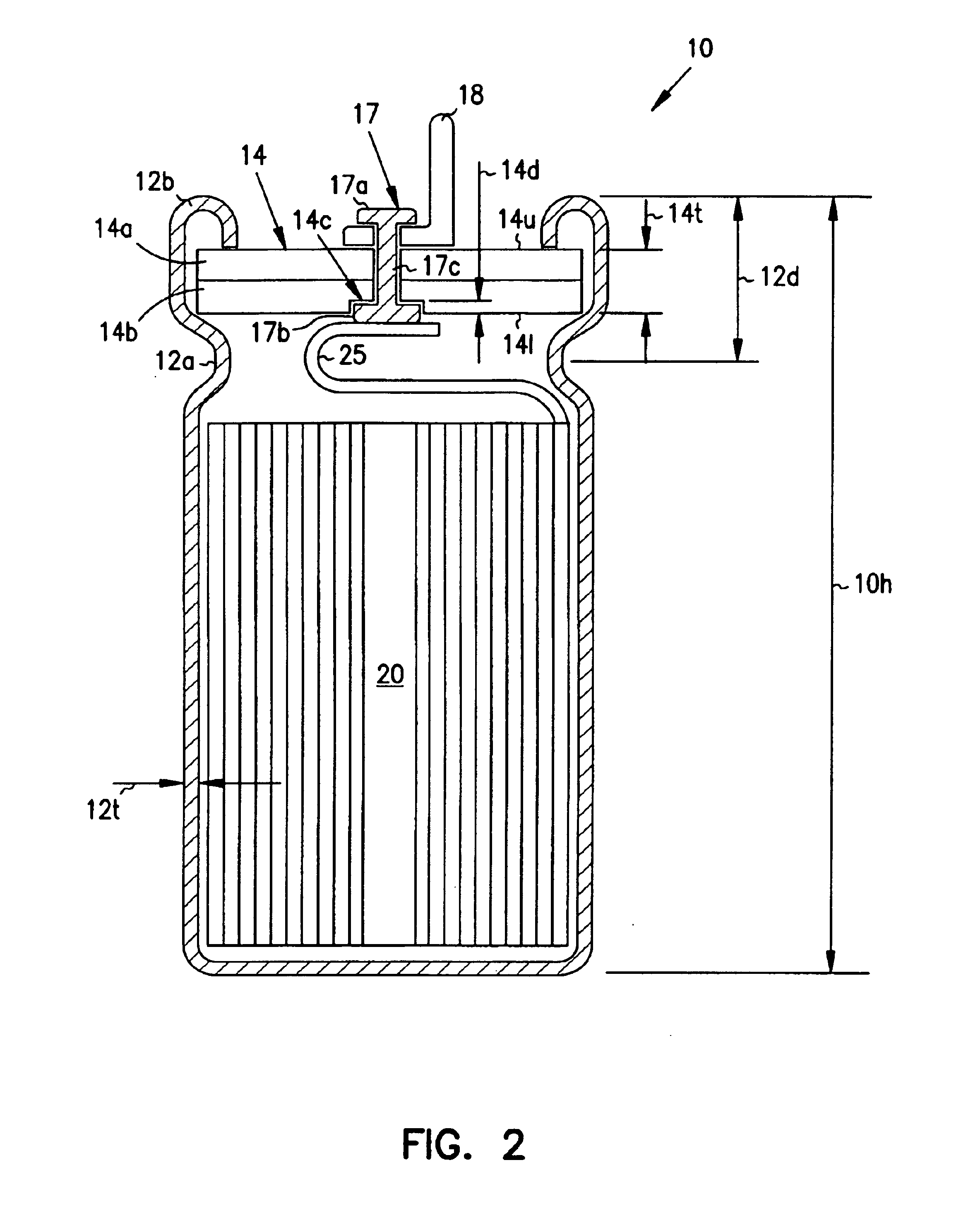
Aluminum case 12 includes a circumferential seating groove 12a and a rolled lip 12b which secure header assembly 14 within an otherwise open end of case 12. (In this exemplary embodiment, an aluminum plate fused or formed integrally with case 12 closes the opposite end, or bottom of case 12. However, in other embodiments it could be advantageous to close the bottom end with a second header assembly.) Seating groove 12a has an exemplary radius of about 0.035 inches. Lip 12b, which can be formed by rolling over the top edge of case 12, has an exemplary radius of about 0.015 inches. FIG. 2 also shows that seating groove 12a is a distance 12d, for example 0.145 inches, from rolled lip 12b.
FIG. 2, a cross-section taken along line 2—2 in FIG. 1, generally shows that case 12, which has a thickness 12t, houses an active element 20. Active element 20 conventionally comprises a rolled assembly of an anode foil, a cathode foil, and at least one insulative separator, with each foil connected r...
PUM
 Abstract
Description
Claims
Application Information