
System method and network for providing high speed remote access from any location connected by a local loop to a central office

a technology of remote access and system method, applied in the field of telecommunication networks, can solve the problem of limited bandwidth of each remote access connection, and achieve the effect of high speed

Inactive Publication Date: 2005-02-08
GC PIVOTAL LLC
View PDF71 Cites 21 Cited by
  • Summary
  • Abstract
  • Description
  • Claims
  • Application Information

AI Technical Summary

Benefits of technology

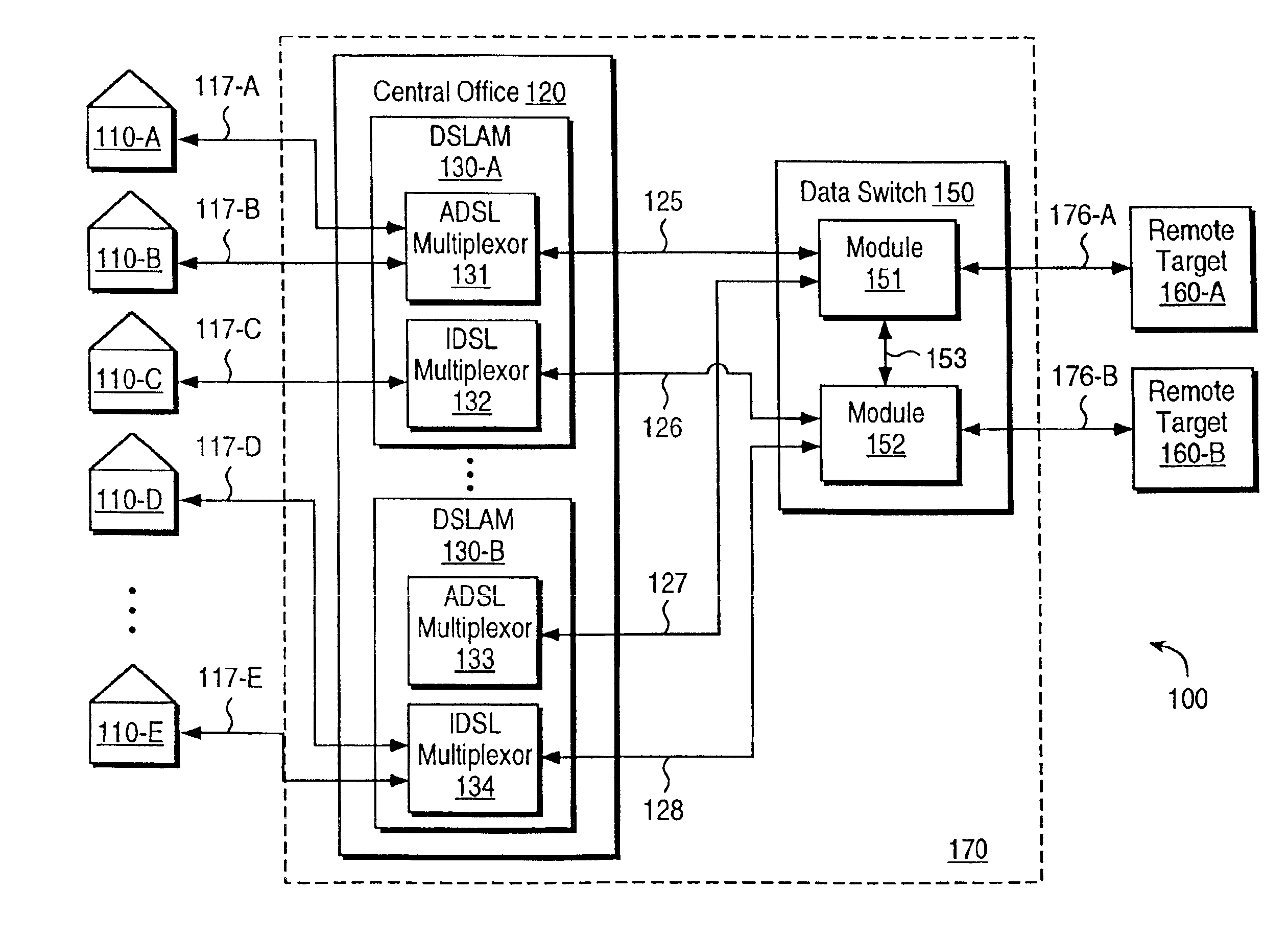
The present invention enables high speed remote access to be provided to any location connected to a central office in a cost effective manner. Connections with a bandwidth of 128 Kbps or 144 Kbps can be provided to any location connected to a central office by a local loop. Connections with bandwidth much higher than 128 Kbps or 144 Kbps can optionally be provided to some of the locations. Connections with such high bandwidth are provided using shared equipment and transmission facilities, thereby enabling all the connections to be provided in a cost-effective manner.
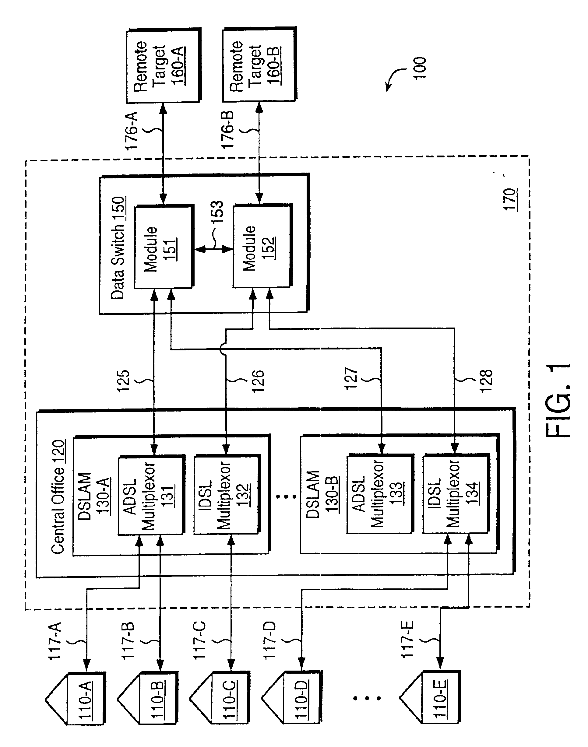
A telecommunication network is employed to provide high speed remote access in accordance with the present invention. The telecommunication network includes access multiplexors and data switches. The access multiplexors are located in a central office and provide interfaces for local loops connected using IDSL technology and another DSL signaling technology. The IDSL signaling technology provides the 128 Kbps or 144 Kbps bandwidth. As the local loops to any location can be used with IDSL signaling, 128 Kbps or 144 Kbps bandwidth can be provided to any location. The another DSL (e.g., ADSL) technology can provide for much higher speed transfers.
The data switches deliver the data of the packets to a destination remote target. The destination remote target is typically determined based on the address contents of the packets. The data switch may perform any conversions necessary (e.g., from cells to frames and vice versa) so that the data can be delivered using a shared communication bandwidth pipe. That is, the data in all packets can be delivered to a destination remote target using one shared pipe so that economies of scale can be realized. Data is transmitted in the reverse direction from the remote targets to the locations, enabling remote access connections to be established.
The present invention enables a bandwidth of 128 Kbps or 144 Kbps to be supported on the interface to any location connected to a central office. In addition, some of the locations can be provided even higher bandwidth. This is enabled by using IDSL technology in combination with other DSL technologies providing higher bandwidth.

Problems solved by technology

As is well known in the art, the bandwidth on each remote access connection is limited by the least bandwidth available in a communication path.

Method used


Image

  • System method and network for providing high speed remote access from any location connected by a local loop to a central office
  • System method and network for providing high speed remote access from any location connected by a local loop to a central office
  • System method and network for providing high speed remote access from any location connected by a local loop to a central office

Examples


Embodiment Construction

0. Definitions and Glossary of Terms

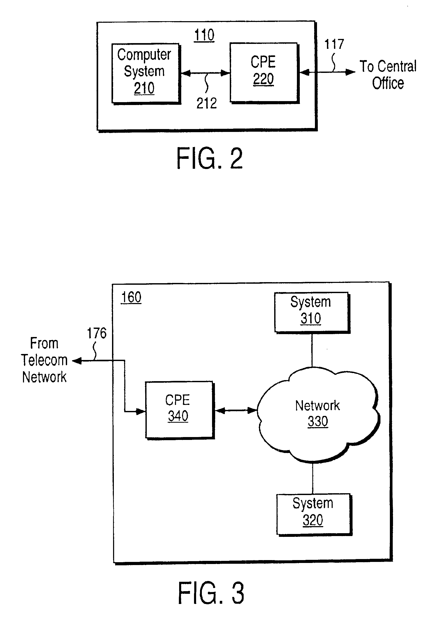
The following are the definitions of some of the terms used in the present patent application.Location: Entities such as homes and businesses connected to a central office by a local loop.Central office: In the U.S. Telecommunication industry, a central office commonly refers to a place where local loops connecting to different locations originate.Local loop: Physical connection providing connectivity to a central office from a location. Each local loop typically includes a metallic (e.g., copper) wire pair connecting to a location. The physical connection to a central office may include equipment such as repeaters and / or a digital loop carrier (DLC) in the connection path.Target: A place where remote systems are placed and accessed by users at locations using telecommunication network and local loops.IDSL Technology: One of the DSL technologies well known in the industry, typically implemented using ISDN signaling scheme. Present (as of May 1998)...


PUM


Abstract

A telecommunication system for providing a remote access connection having a bandwidth of 128 Kbps or 144 Kbps to any location (homes, small businesses, etc.) connected to a central office by a local loop, and higher bandwidth for some locations. The 128 Kbps or 144 Kbps is provided using ISDN Digital Subscriber Loop (IDSL) technology and higher bandwidth using other DSL technologies such as ADSL. Using shared equipment and transmission facilities, the present invention enables the high-speed remote access connections to be provided in a cost effective manner.

Description

BACKGROUND OF THE INVENTION1. Field of the InventionThe present invention relates to telecommunication networks, and more specifically to a system, method, and network for providing high speed remote access from any location connected by a local loop to a central office.2. Related ArtRemote access generally refers to the ability of a user to access a remote system using a local system (e.g., a personal computer). The remote system can be either a stand-alone system or a network of systems. Mainframe computers such as those available from International Business Machines is an example of a stand-alone system. A network connecting several systems such as printers, modems, servers, computer systems, telecommunication equipment, among others, is an example of a network of systems. Remote access is commonly referred to as internet access when a local system accesses a remote network of systems such as what it known as world-wide-web.Remote access typically requires transferring digital da...

Claims


Application Information

Patent Timeline
Patent Type & Authority Patents(United States)
IPC IPC(8): H04M11/06
CPCH04M11/062
Inventor RAWSON, RICHARD ALVANREILLY, JOHN CHARLESRAMACHANDRAN, RANGASWAMY
Owner GC PIVOTAL LLC
Learn More