Systems and methods for multiple winding impulse frequency response analysis test

a technology of impulse frequency response and system and method, applied in hydrodynamic testing, instruments, nuclear elements, etc., can solve the problems of large current flow, undesirable transformer fault, large fault current flowing through the transformer,

Inactive Publication Date: 2005-02-08
GEORGIA TECH RES CORP
View PDF12 Cites 16 Cited by
  • Summary
  • Abstract
  • Description
  • Claims
  • Application Information

AI Technical Summary

Problems solved by technology

Transformer faults are undesirable for at least two major reasons.
First, end users may become separated from the energy delivery system, thereby loosing their electrical service.
Second, transformer faults may result in large magnitudes of current flow, known as fault current, across the breach and through the transformer windings.
Also, faults occurring on the energy delivery system at locations relatively close to the transformer may result in large fault currents flowing through the transformer.
Such fault currents may cause severe physical damage to the transformer.
Such winding deformation and/or displacement can cause over-voltage stresses on portions of the winding insulation and exacerbate the process of the naturally occurring deterioration of the winding insulation that occurs over a period of time.
The fault current may further increase damage to the insulation, or damage insulation of adjacent windings, thereby increasing the magnitude and severity of the fault.
In the most extreme cases, the fault current may cause an ignition in the transformer oil, resulting in a breach of the transformer casing and a subsequent fire or explosion.
Once a transformer fault occurs, it is usually too late to minimize transformer damage and to reduce t

Method used


Image

  • Systems and methods for multiple winding impulse frequency response analysis test
  • Systems and methods for multiple winding impulse frequency response analysis test
  • Systems and methods for multiple winding impulse frequency response analysis test

Examples


Embodiment Construction

A. Overview of the Transformer Testing System and Method

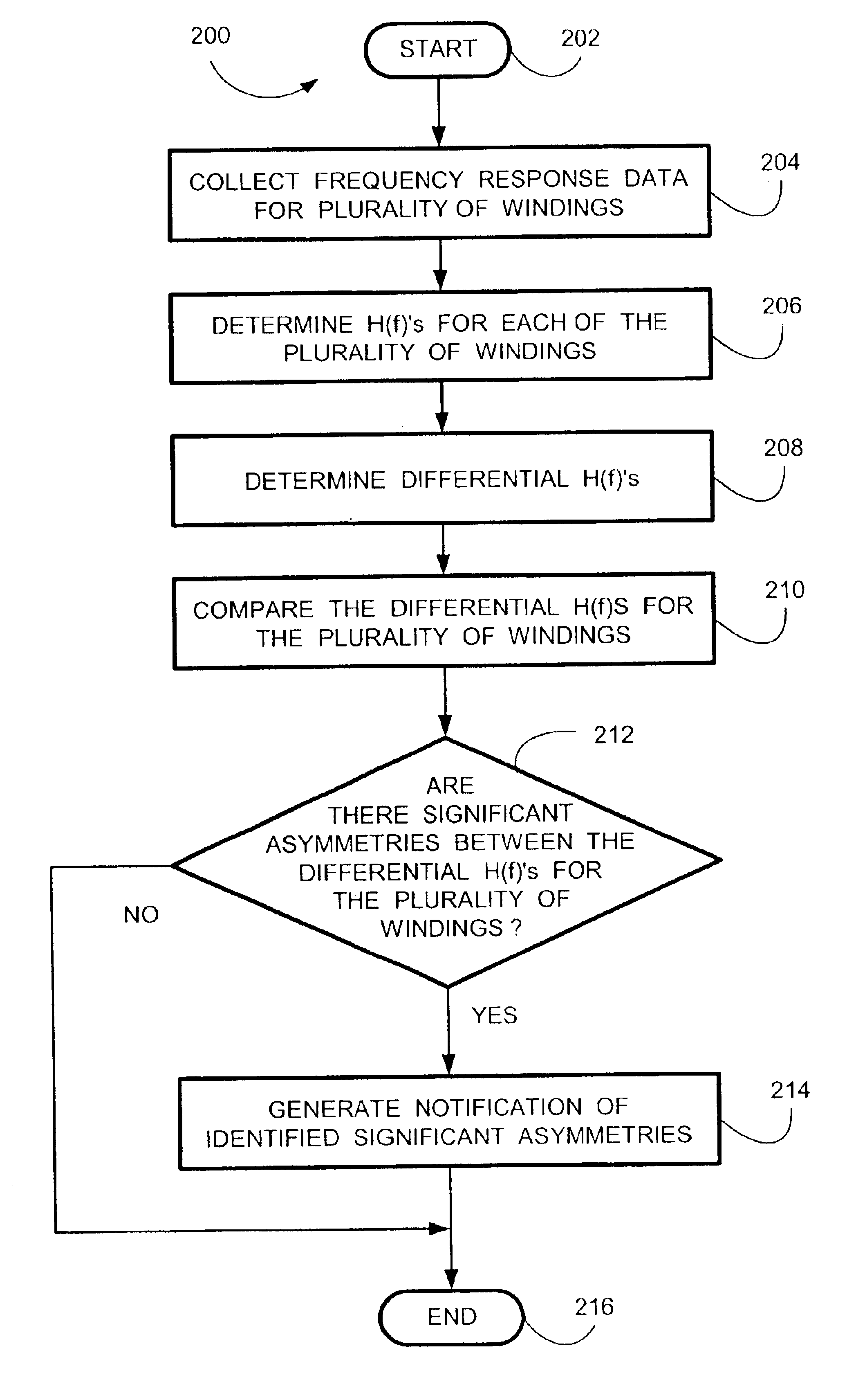
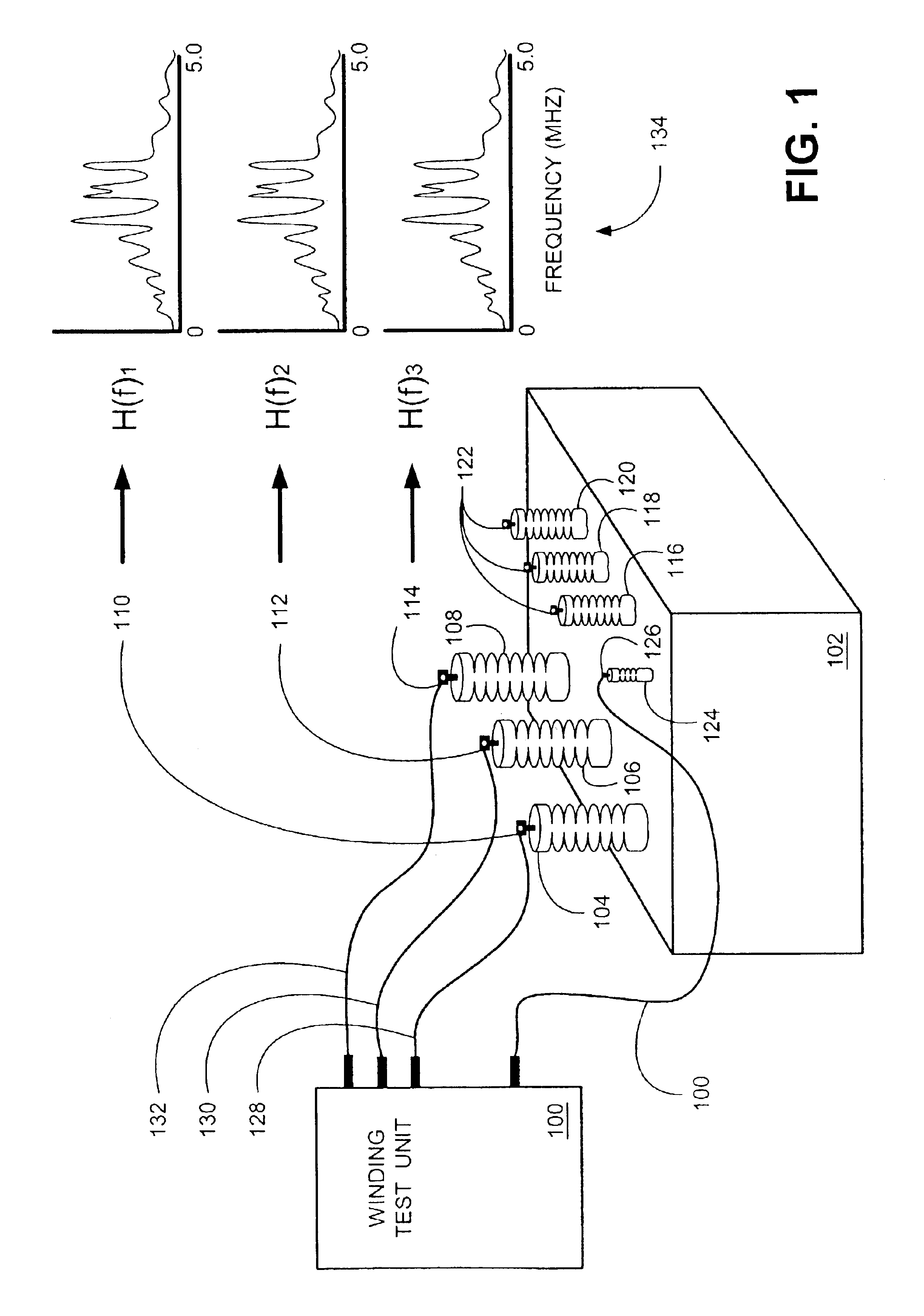
FIG. 1 is a simplified conceptual diagram of an embodiment of a winding test unit 100 coupled to a transformer 102. Winding test unit 100 provides for determining normal and / or abnormal characteristic signatures of same-voltage windings residing in a device, such as transformer 102, without the need for a comparison to past historical data, and, in one embodiment, without the need for subjective expert opinions, by identifying significant asymmetries in differential characteristic signatures [H(f)'s]. Differential H(f)'s are, in one embodiment, determined by computing the difference between pairs of H(f)'s determined for a plurality of transformer windings.

Transformer 102 is a well known voltage conversion device employed in energy delivery systems. Transformer 102 is illustrated for convenience as a three phase transformer unit as having three high voltage bushings 104, 106 and 108. For simplicity, detailed operation of the tr...


PUM


Abstract

The winding testing unit provides systems and methods for determining normal and/or abnormal characteristic signatures of same-voltage windings residing in a device, such as transformer, without the need for a comparison to past historical data. A plurality of characteristic signatures [H(f)'s] are determined for each of a plurality of windings. A plurality of differential characteristic signatures [H(f)'s] are then determined from a plurality of H(f) pairs selected from the plurality of H(f)'s. The differential H(f)'s are compared and at least one significant asymmetry is identified between the differential H(f)'s.

Description

TECHNICAL FIELDThe present invention relates generally to energy delivery systems, and more particularly, to systems and methods for testing winding and winding connection displacements in a transformer.BACKGROUND OF THE INVENTIONElectric utilities and other organizations are responsible for supplying an economic, reliable and safe source of electricity. Three major components are employed in an energy delivery system to provide the electricity to the end user, the generator, the transmission line and the transformer.The transformer is a device that changes voltage or a power angle. Generally, voltage from the generator is a lower voltage than used by the transmission lines that transmit the electricity to the end user. Furthermore, the voltage used by the end user is much lower than voltage used by the transmission lines. Thus, one exemplary purpose of the transformer is to couple elements of an energy delivery system that operate at different voltages.Transformers come in many dif...

Claims


Application Information

Patent Timeline
IPC IPC(8): G01R31/06G01R31/02
CPCG01R31/027G01R31/62
Inventor COFFEEN, LARRY T.
Owner GEORGIA TECH RES CORP
Why Eureka
Try Eureka