Blade clamp mechanism

a clamping mechanism and blade technology, applied in the direction of power driven reciprocating saws, metal sawing devices, manufacturing tools, etc., can solve the problems of difficult manufacturing of integral cams, laborious operation of the clamping mechanism, and relatively large manufacturing errors of components included in the clamping mechanism, etc., and achieve the effect of simple structur

Inactive Publication Date: 2005-02-15
POSITEC POWER TOOLS (SUZHOU) CO LTD
View PDF13 Cites 46 Cited by
  • Summary
  • Abstract
  • Description
  • Claims
  • Application Information

AI Technical Summary

Benefits of technology

It is an object of the present invention to provide a keyless blade clamp mechanism with a simple structure.
The keyless blade clamp mechanism of the present invention includes a base, a sliding block slidably disposed on the base and a clamping lever pivotally connected to the base. On one pivot side of the clamping lever is a clamp plate and on the other pivot side of the clamping lever is a plate. The base has a supporting surface opposing the clamp plate. In use, the sliding block slides to engage and press the plate causing the clamp plate to tilt and a gap to appear between the clamp plate and the supporting surface to permit a saw blade to be inserted into (or be pulled out of) the gap. The present invention has the advantage that few components are involved and it is easily manufactured at low cost.

Problems solved by technology

The inner cam surface presses directly on the outer cam surface to actuate the movement in the radial direction therefore the clamping mechanism is laborious to operate.
Furthermore, the components included in the clamping mechanism are subject to relatively large manufacturing errors and the integral cam is difficult to manufacture.

Method used


Image

  • Blade clamp mechanism
  • Blade clamp mechanism
  • Blade clamp mechanism

Examples


Embodiment Construction

It will be readily understood that the isolated protein sequences and methodologies of the present invention, as generally described and illustrated in the Figures herein, could be arranged and designed in a wide variety of different configurations. Those of ordinary skill in the art will, of course, appreciate that various modifications to the details herein may be made without departing from the essential characteristics of the invention, as described. Thus, the following more detailed description of the embodiments of the isolated protein sequences and methodologies of the present invention, as represented in FIGS. 1-5, is not intended to limit the scope of the invention, as claimed, but it is merely representative of the presently preferred embodiments of the invention.

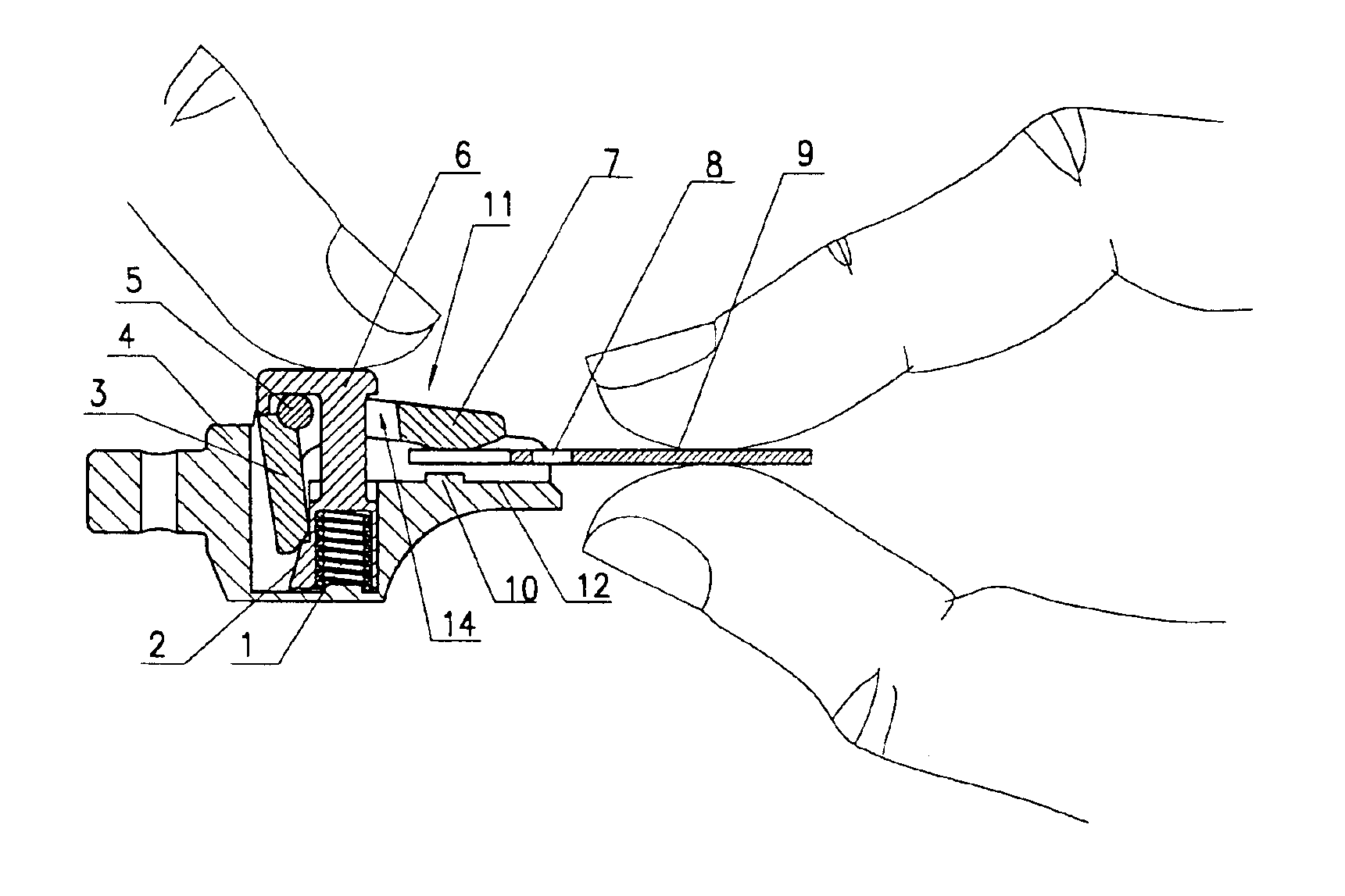
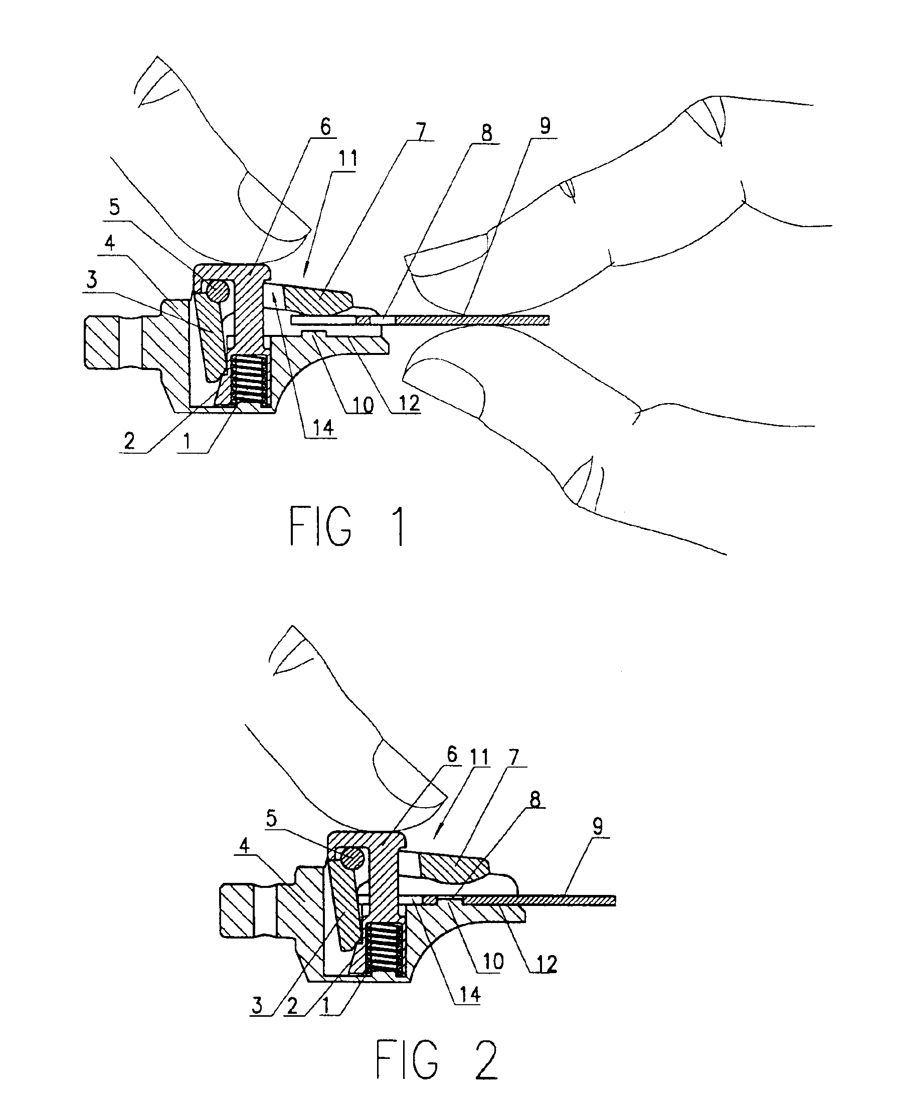
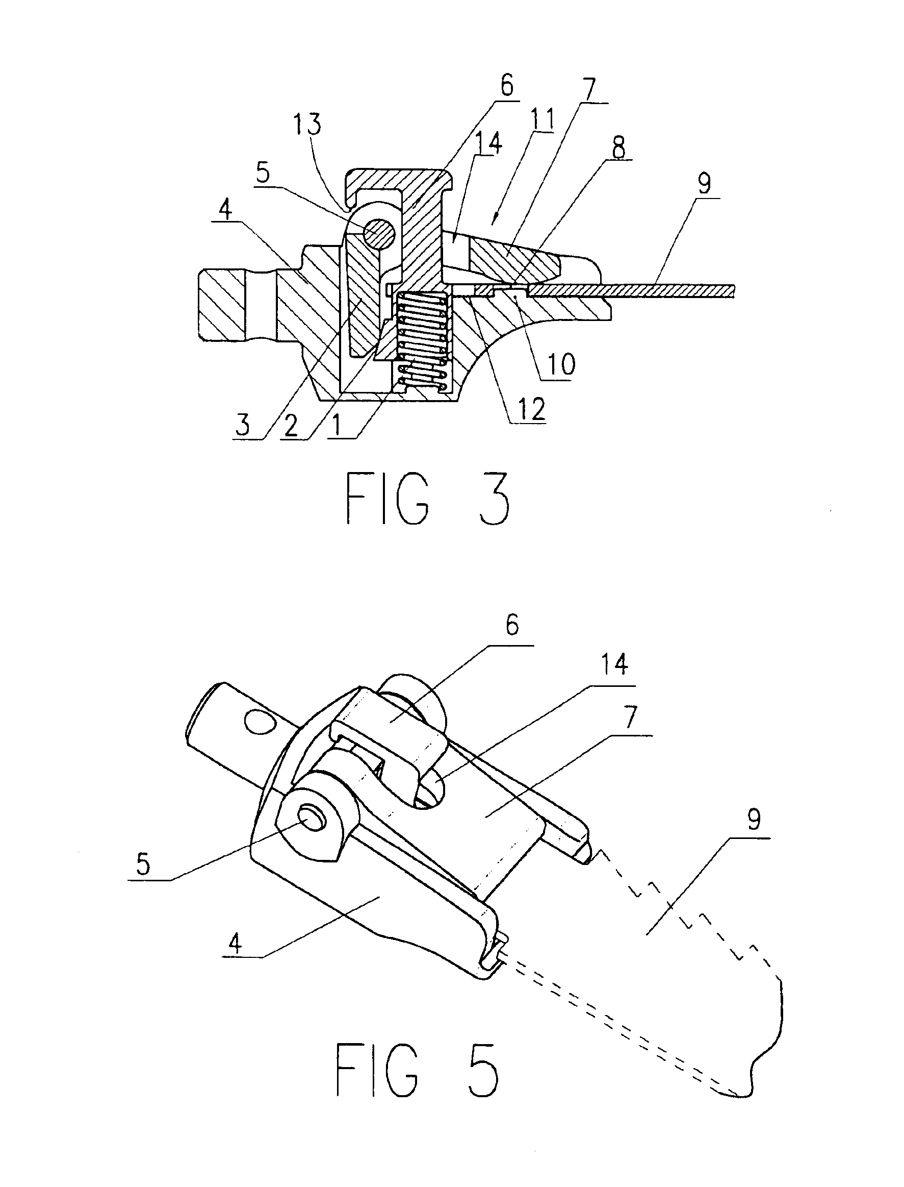
FIGS. 1, 2 and 3 show a sectional view of an embodiment of the blade clamp mechanism of the present invention during and after insertion of a saw blade 9 in clamping and non-clamping positions. The blade clamp mec...


PUM

PropertyMeasurementUnit
elasticaaaaaaaaaa
movementaaaaaaaaaa
linear restoring forceaaaaaaaaaa

Abstract

The present invention relates to a keyless blade clamp mechanism including a base, a sliding block slidably disposed on the base and a clamping lever pivotally connected on the base. On one pivot side of the clamping lever is a clamp plate and on the other pivot side of the clamping lever is a plate. The base has a supporting surface opposing the clamp plate. In use, the sliding block slides to engage and press the plate causing the clamp plate to pivot and a gap to appear between the clamp plate and the supporting surface to permit a saw blade to be inserted into (or be pulled out of) the gap. The present invention has the advantage that few components are involved and it is easily manufactured at low cost.

Description

BACKGROUND1. Technical Field of the InventionThe present invention relates to a blade clamp mechanism (e.g., a keyless blade clamp mechanism) and to a cutting assembly (such as a saw) comprising the blade clamp mechanism.2. The Background ArtU.S. Pat. No. 6,209,208 discloses a clamping mechanism which comprises a driving subassembly with an outer cam surface and an inner cam surface and a locking subassembly. The locking subassembly includes an outer follower surface adapted to be driven by the outer cam surface and an inner follower surface adapted to be driven by the inner cam surface whereby the locking subassembly is moved in the radial direction and locks the blade when the driving subassembly rotates. The inner cam surface presses directly on the outer cam surface to actuate the movement in the radial direction therefore the clamping mechanism is laborious to operate. Furthermore, the components included in the clamping mechanism are subject to relatively large manufacturing e...

Claims


Application Information

Patent Timeline
Patent Type & Authority Patents(United States)
IPC IPC(8): B23D51/10B23D51/00
CPCB23D51/10Y10T279/17769
Inventor HUAN, HAICHUN
Owner POSITEC POWER TOOLS (SUZHOU) CO LTD
Why Eureka
Try Eureka