Apparatus and method for monitoring compaction

a compaction and apparatus technology, applied in the field of well monitoring, can solve the problems of reducing bandwidth and bending, and achieve the effects of increasing bandwidth, reducing bend, and increasing compression

Inactive Publication Date: 2005-02-15
SHELL USA INC
View PDF15 Cites 59 Cited by
  • Summary
  • Abstract
  • Description
  • Claims
  • Application Information

AI Technical Summary

Benefits of technology

The invention is also an apparatus, system, and method for detecting and measuring compressional strains in a well in real-time without physical intervention. The invention is a fiber gauge system incorporated into a structure to be monitored; a passive sensor constantly activated, provides monitoring of compaction, and permits awareness of well problems without having to physically intervene. The system may be either continuously monitored or monitored periodically without entering the well or altering the well in any way. The system comprises one or more fiber Bragg gratings integ...

Problems solved by technology

In the case of “loop” shaped sensors, an increase in compres...

Method used


Image

  • Apparatus and method for monitoring compaction
  • Apparatus and method for monitoring compaction
  • Apparatus and method for monitoring compaction

Examples


example

In the Example a fiber laser, FineTune™, commercially available from Bragg Photonics, was subjected to bending. The specifications of the fiber laser were as follows:

PARAMETERSSPECIFICATIONSOperationC-BandWavelengthTunable Laser>25 nmWavelength (nm)Laser Linewidth (kHz)<100Tunable Resolution (nm)0.035Wavelength Stability (nm)0.06 Wavelength Accuracy (nm)0.05 Output Power (mW) 5 StandardHigher power optionalConnectorFC / APC

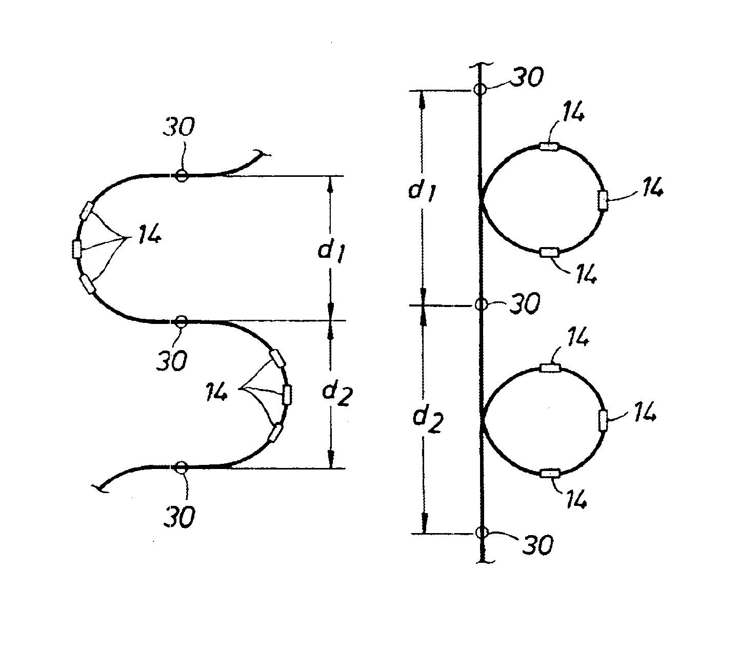
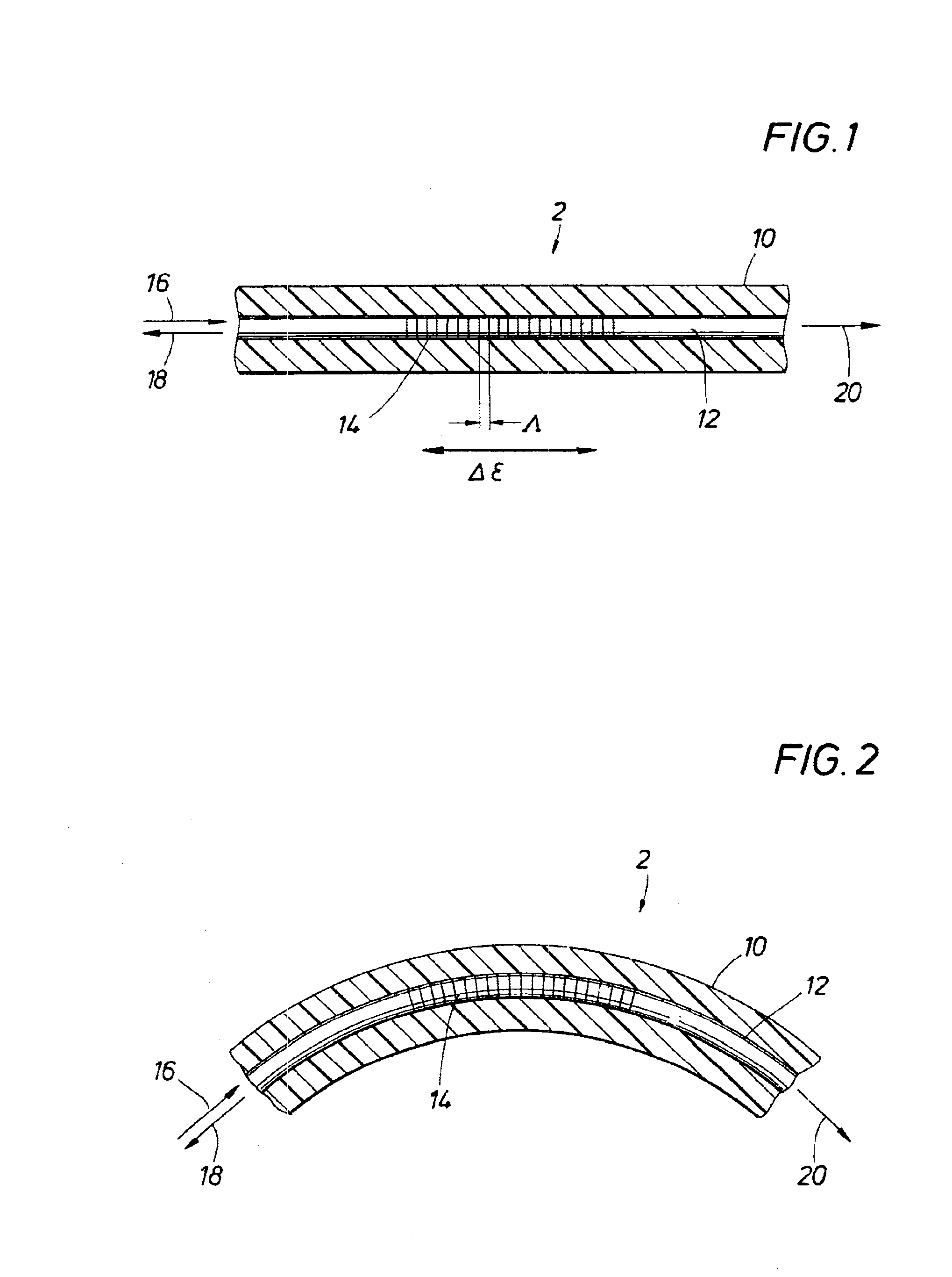
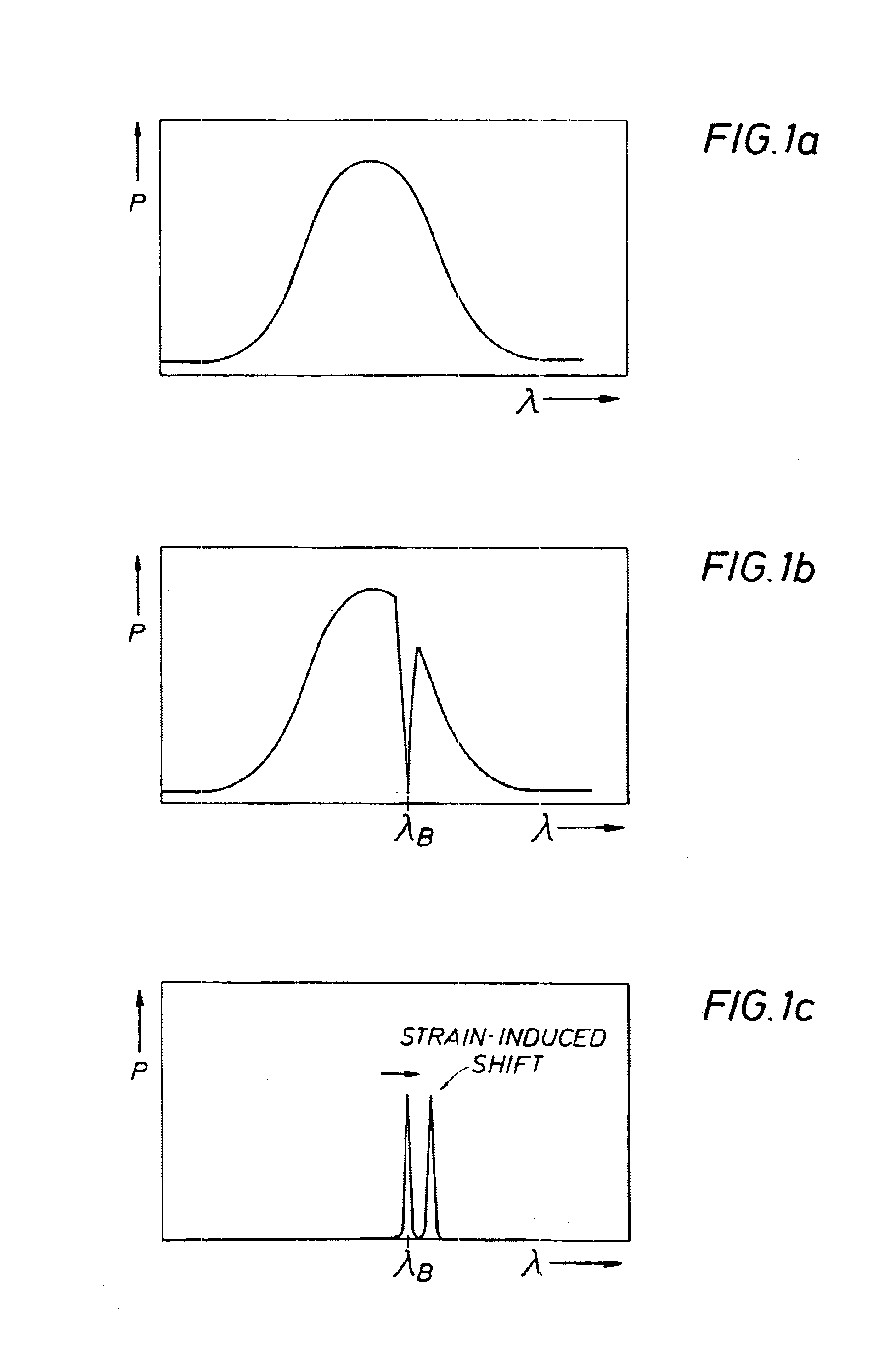
In this fiber the gratings were perpendicular to the fiber axis and rotation of the fiber did not affect results. With respect to polarization of light and bend there was complete axiosymetry around the fiber. For the bent Bragg grating fibers the equation, which describes the Delta Lamda (change in wavelength), at any given radius of curvature (R) is: Δ⁢ ⁢λ=2⁢neff⁢T·ΛR+T / 2

where

Δλ=increase in width of wavelength spectrum

neff=effective index of refraction of fiber

T=thickness of the fiber Bragg grating


PUM


Abstract

An apparatus and method for continuous, passive detection and measurement of tensile and compressional strain in a structure utilizing a shielded optic fiber, the optic fiber having one or more Bragg gratings thereon, the gratings and shield being disposed in a curved path on the structure and a baseline response for the grating is made using an optical source and detector. Changes in tensile or compressional forces on the structure will result in changes in the curve of the grating, resulting in a frequency shift for the returned light.

Description

FIELD OF THE INVENTIONThis invention is related to well monitoring. More particularly it is related to the detection and measurement of compressional strains, or any large displacement, in casing and well completions. Still more particularly, it is related to a new application for fiber optic sensors comprising attaching passive, uniquely configured, fiber optic sensors, enclosed in a protective sheath, to the inner or outer wall of a well casing to measure its deformation and warn of impending problems or failures. The invention utilizes fiber Bragg gratings subjected to bending which are characterized by a measurable broadening of the reflected frequency peak and, when subjected to compression forces, deform on a scale which would be more expected for a large structure such as a well. In another embodiment of the invention, a loop configuration, the fiber Bragg gratings may exhibit a measurable narrowing of the reflected frequency with compaction forces.BACKGROUND OF THE INVENTION...

Claims


Application Information

Patent Timeline
IPC IPC(8): G01B11/16G01D5/353G01L1/24G01D5/26
CPCG01B11/18G01L1/246G01D5/35303G01D5/35316
Inventor RAMBOW, FREDERICK HENRY KREISLERDRIA, DENNIS EDWARDSTEWART, DAVID RALPH
Owner SHELL USA INC
Why Eureka
Try Eureka