Power take-off assembly of a working vehicle

a technology of working vehicle and power take-off assembly, which is applied in the direction of auxiliary drives, control devices, gears, etc., can solve the problems of affecting the operation of the working vehicle, changing the rotary speed of the output sleeve, and the actuator is not suited to the working vehicle having a lever-operated operation, so as to achieve easy change of the specification of the power take-off assembly and increase the size of the arrangemen

Inactive Publication Date: 2005-02-15
YANMAR CO LTD
View PDF14 Cites 29 Cited by
  • Summary
  • Abstract
  • Description
  • Claims
  • Application Information

AI Technical Summary

Benefits of technology

[0011]The actuator connects the low speed gear to the output sleeve when the splined end having the greater number of teeth is inserted into the output sleeve so as to make the splined end having the fewer teeth project outward from the vehicle, thereby rotating the PTO shaft at the predetermined low speed. In this state, since the actuator holds the second collar, the shifter collar is held in place so as to prevent an attached working implement from being unexpectedly driven at high speed while the splined end having the fewer teeth projects outward, thereby ensuring safety. If the PTO shaft is disposed so as to make the splined end having the greater number of teeth project outward from the vehicle, the shifter collar is allowed to slide so as to connect the high speed gear to the output sleeve so that the output sleeve may be rotated at the predetermined high speed. Even if the output sleeve remains rotating at the low speed, it is not a safety problem.
[0012]Since the actuator, which is actuated by an end surface of the PTO shaft when the splined end having the more teeth is inserted into the output sleeve, attempts to hold the second collar disposed on the inner end of the output sleeve so as to hold the shifter collar at its low speed position, the actuator comes to be disposed correspondingly to the inner end of the output sleeve apart from the transmission system to the PTO shaft. Accordingly, the actuator does not increase the size of the arrangement for speed changing of the output sleeve. The shifter collar may be also used if it is operated for speed changing of the output sleeve by a lever without the actuator, so that the power take-off assembly specification can be changed easily.
[0014]Due to this construction, when the output sleeve engages with the high speed gear so as to be rotated at high speed, the PTO shaft is prevented from being set into such a low speed rotation mode that the splined end thereof having the greater number of teeth is inserted into the output sleeve and the splined end thereof having the fewer teeth projects outward. That is, safety is ensured by preventing the splined end having fewer teeth from projecting outward from the vehicle unless the shifter collar and the second collar are returned to their low speed position where the low speed gear engages with the output sleeve. Such a power take-off assembly has the same advantage mentioned above.
[0019]Since the collar is disposed on the inner end of the output sleeve and slid to engage selectively one of the high and low speed gears with the output sleeve by the actuator including the pin whose position in the axial direction of the output sleeve is changed correspondingly to the insertion state of the PTO shaft into the output sleeve, the actuator comes to be located at a position corresponding to the inner end of the output sleeve so as not to increase the size of the speed changing arrangement for the output sleeve. The collar may be also operated by a lever without the actuator so as to be also usable for a power take-off assembly whose output sleeve is changed in rotary speed by operating a lever without the actuator, thereby facilitating changes in the specifications of the power take-off assembly.
[0021]As a preferable aspect for selectively connecting one of the high and low speed gears to the output sleeve through the collar, on the assumption that one of the high and low speed gears is disposed further outward than the other so as to serve as an outer gear and the other serves as an inner gear, a boss portion of the outer gear is extended along the output sleeve toward said collar so that a toothed portion is formed on the outer peripheral surface of the extended boss portion thereof. Correspondingly, a toothed portion is formed on the inner peripheral surface of the collar so as to be enabled to mesh with the toothed portion of the outer gear. A bearing is interposed between the inner gear and the boss portion of the outer gear so as to freely rotatably dispose the inner gear around the boss portion of the outer gear. The inner gear has a projecting portion which projects from the bearing along the output sleeve toward the collar. A toothed portion is formed on the inner peripheral surface of the projecting portion of the inner gear, and correspondingly, a toothed portion is formed on the outer peripheral surface of the collar so as to be enabled to mesh with the toothed portion of the inner gear. In this construction, the two toothed portions of the collar are formed on the outer and inner peripheral surfaces, respectively, thereby reducing the sliding range of the collar in comparison with the case where the two toothed portions of the collar are formed on one of the outer and inner peripheral surfaces thereof. Thus, the axial length of the output sleeve is allowed to be extremely reduced.

Problems solved by technology

However, such an actuator interposed in the PTO driving system tends to increase the size of the PTO speed changing arrangement which changes the rotary speed of the output sleeve.
Furthermore, the actuator is not suited to a working vehicle having a lever-operated speed changing mechanism for the output sleeve.

Method used


Image

  • Power take-off assembly of a working vehicle
  • Power take-off assembly of a working vehicle
  • Power take-off assembly of a working vehicle

Examples


first embodiment

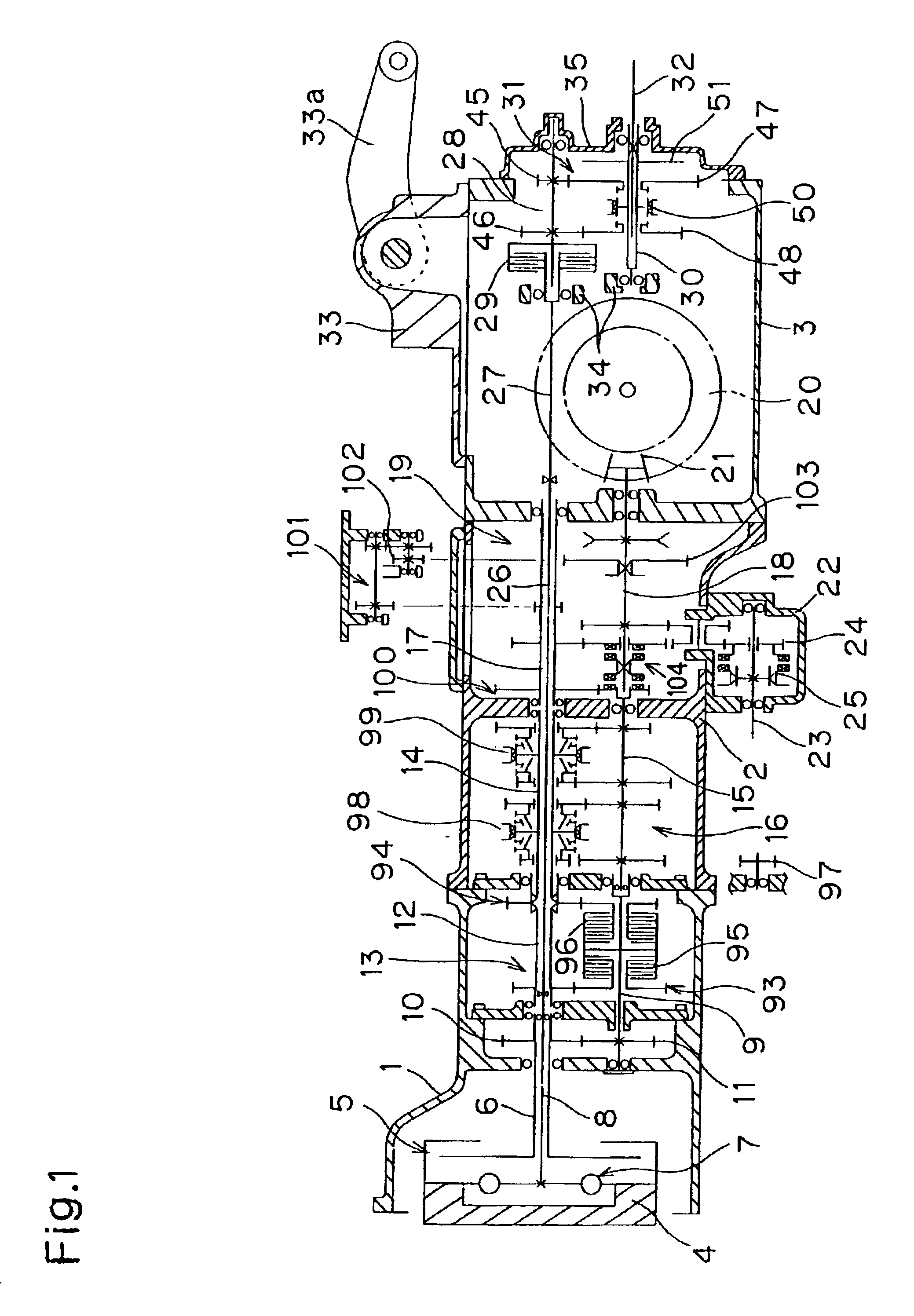
[0040]Description will be given of the present invention shown in FIGS. 1-11. Referring to a transmission system of a tractor shown in FIG. 1, a front housing 1, a main housing 2 and a rear housing 3 are continuously joined to one another from ahead to behind so as to constitute a transmission housing of the tractor.

[0041]Front housing 1 incorporates an engine flywheel 4 at the foremost area therein, a main traveling-driving sleeve 6 connected to flywheel 4 through a main clutch 5, and a main PTO-driving shaft 8 connected to flywheel 4 through a buffering coupler 7.

[0042]A driving shaft 9 is disposed below sleeve 6. Sleeve 6 and shaft 9 are drivingly connected to each other through mutually meshing gears 10 and 11. A driven sleeve 12 is disposed coaxially with sleeve 6. A high / low speed changing assembly 13 is interposed between driving shaft 9 and driven sleeve 12. In a front half area of main housing 2, a driving sleeve 14 is disposed coaxially to driven sleeve 12 and connected th...

second embodiment

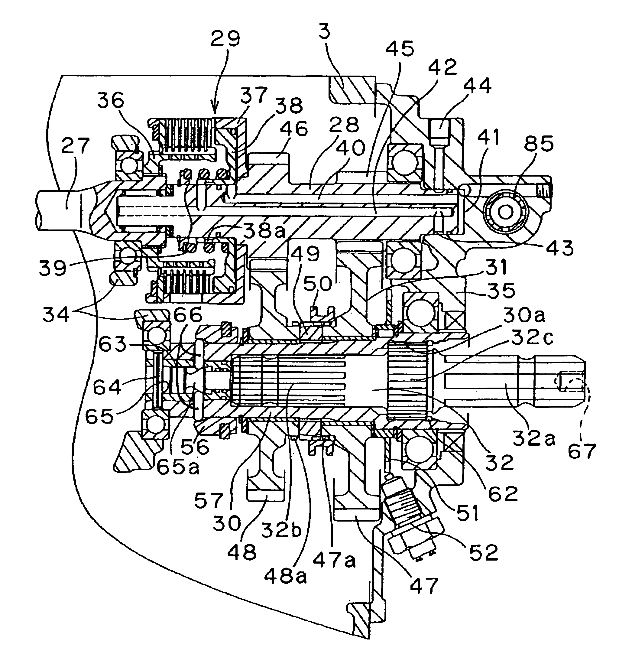
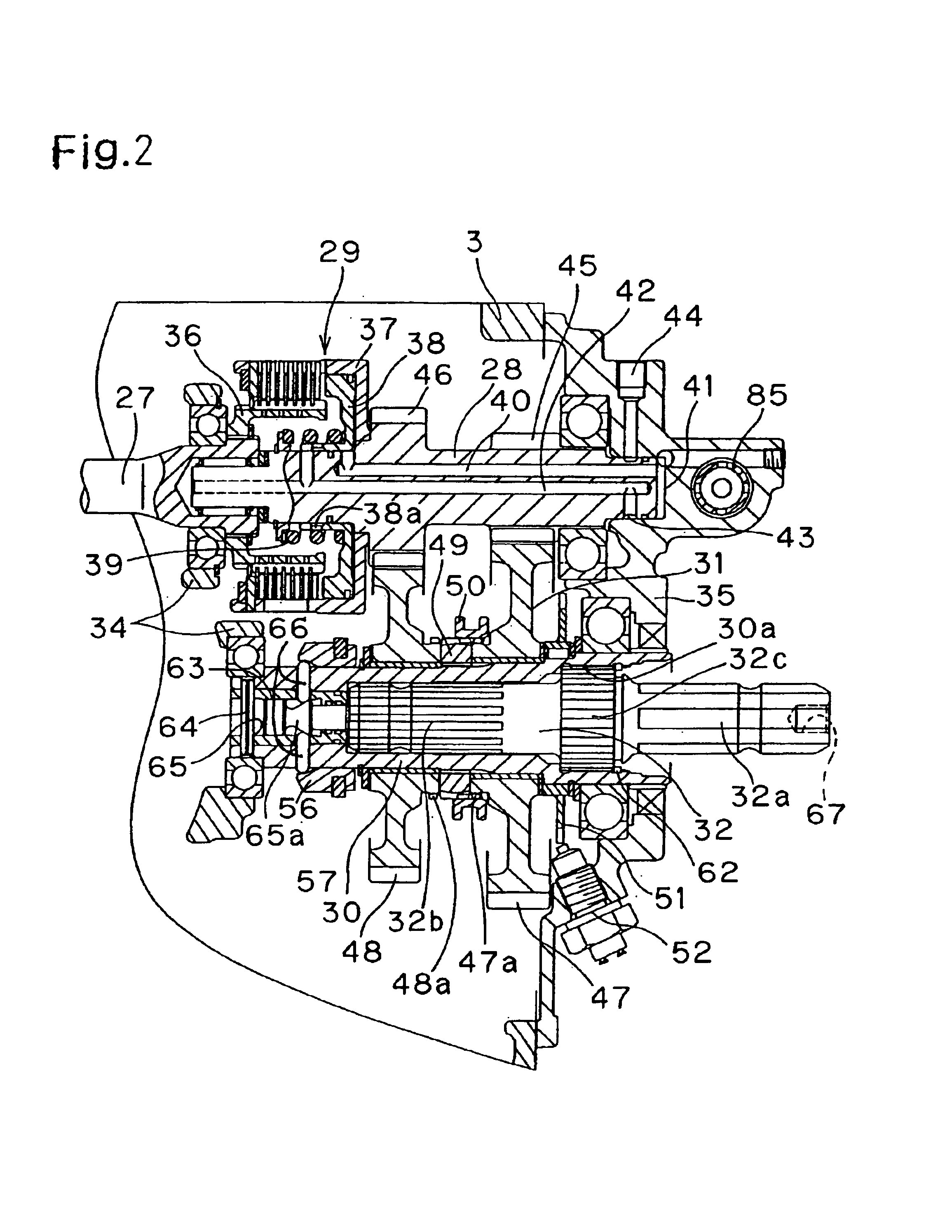
[0076]power take-off assembly shown in FIGS. 14 to 17 is almost similar to the above embodiment. As shown in FIGS. 14 to 16, the different point thereof from the above embodiment is that a collar 150 corresponding to shifter collar 50 is fitted around output sleeve 30 through splines and no member corresponding to collar 56 is provided.

[0077]Gears 47 and 48 are freely rotatably provided around output sleeve 30 so as to constitute PTO speed changing arrangement 31. A boss of gear 47 is greatly extended along output sleeve 30 toward collar 150. An outer periphery of utmost end of the extended boss of gear 47 serves as a toothed portion 47a which is enabled to mesh with a toothed portion 150a formed on an inner peripheral surface of collar 150. Gear 48 is freely rotatably disposed around the boss of gear 47 through a couple of ball bearings 151. A boss of gear 48 projects from bearing 151 toward collar 150 so as to be formed at an inner periphery of utmost end thereof with a toothed po...


PUM


Abstract

A reversible PTO shaft having opposite splined ends whose numbers of teeth are different from each other is inserted at one of the splined ends into an output sleeve and not-relatively rotatably connected to the output sleeve. For constituting at a position out of the PTO transmission system an actuator for changing the rotary speed of the output sleeve and holding the output sleeve changed in rotary speed simultaneously to the reversing of PTO shaft, a second collar connected to a shifter collar for changing the rotary speed of output sleeve so as to be slidable integrally with the shifter collar is disposed on an inner end of the output sleeve. When the splined end of PTO shaft having the greater number of teeth is inserted into the output sleeve, a sensor having a cam surface is moved by an end surface of the PTO shaft so as to make a pin project from the output sleeve, thereby holding the second collar at its low speed position. A power take-off assembly which sets the output sleeve into either a low speed mode or a high speed mode simultaneously to the reversing of the PTO shaft is also disclosed.

Description

BACKGROUND OF THE INVENTION[0002]1. Field of the Invention[0003]The present invention relates to a power take-off assembly provided at a longitudinal end portion of a working vehicle for driving a working implement attached to the end portion of the vehicle. More particularly, it relates to a power take-off assembly comprising an output sleeve, which is variable in rotary speed thereof and disposed at the end portion of the vehicle longitudinally of the vehicle, and a reversible PTO shaft, whose opposite splined ends are different in their number of teeth, wherein, in correspondence to a kind of the attached working implement, one splined end of the reversible PTO shaft is selectively inserted into the output sleeve and not-relatively rotatably connected to the output sleeve so that the other splined end of the PTO shaft projects outward from the vehicle to be drivingly connected to the working implement.[0004]2. Background Art[0005]As disclosed in U.S. Pat. Nos. 3,513,712, 3,352,16...

Claims


Application Information

Patent Timeline
Patent Type & Authority Patents(United States)
IPC IPC(8): B60K17/28
CPCB60K17/28Y10T74/2186
Inventor MATUFUJI, MIZUYAYOSHII, GEN
Owner YANMAR CO LTD
Why Eureka
Try Eureka