Diaphragm valve

Inactive Publication Date: 2005-02-15
IND TECH RES INST
View PDF9 Cites 20 Cited by
  • Summary
  • Abstract
  • Description
  • Claims
  • Application Information

AI Technical Summary

Benefits of technology

In consideration of the above-mentioned problems, this invention provides a diaphragm valve sealing design on semiconductor level and an improved design of a metal dish-type diaphragm set. This diaphragm valve conforms to the requirements of e

Problems solved by technology

This diaphragm valve is designed to achieve driving fit by pressing metal surfaces together, but dust particles are easily generated, due to metal frictions, thus it fails to meet the requirements of super cleanness.2. The American U.S. Pat. No. 6,092,550 reveals a diaphragm valve, which controls the inflow and outflow of fluid bodies by using the driving fit between diaphragms and a non-metal axle ring, instead of a metal one.
The negative part of this is, that the metal axle ring and non-metal axle ring are not maintainable or replaceable, and the fitting

Method used


Image

  • Diaphragm valve
  • Diaphragm valve
  • Diaphragm valve

Examples


Example

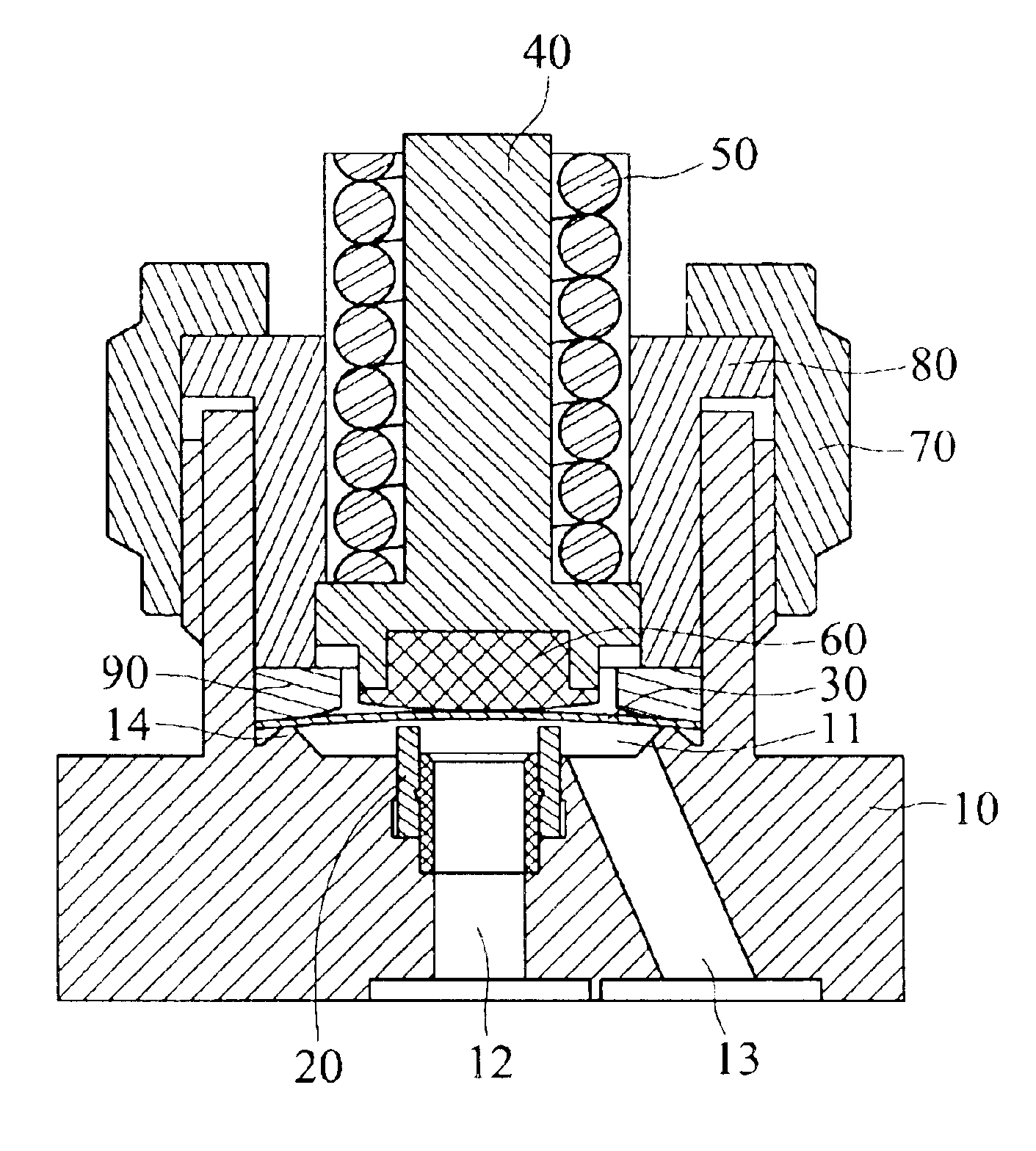
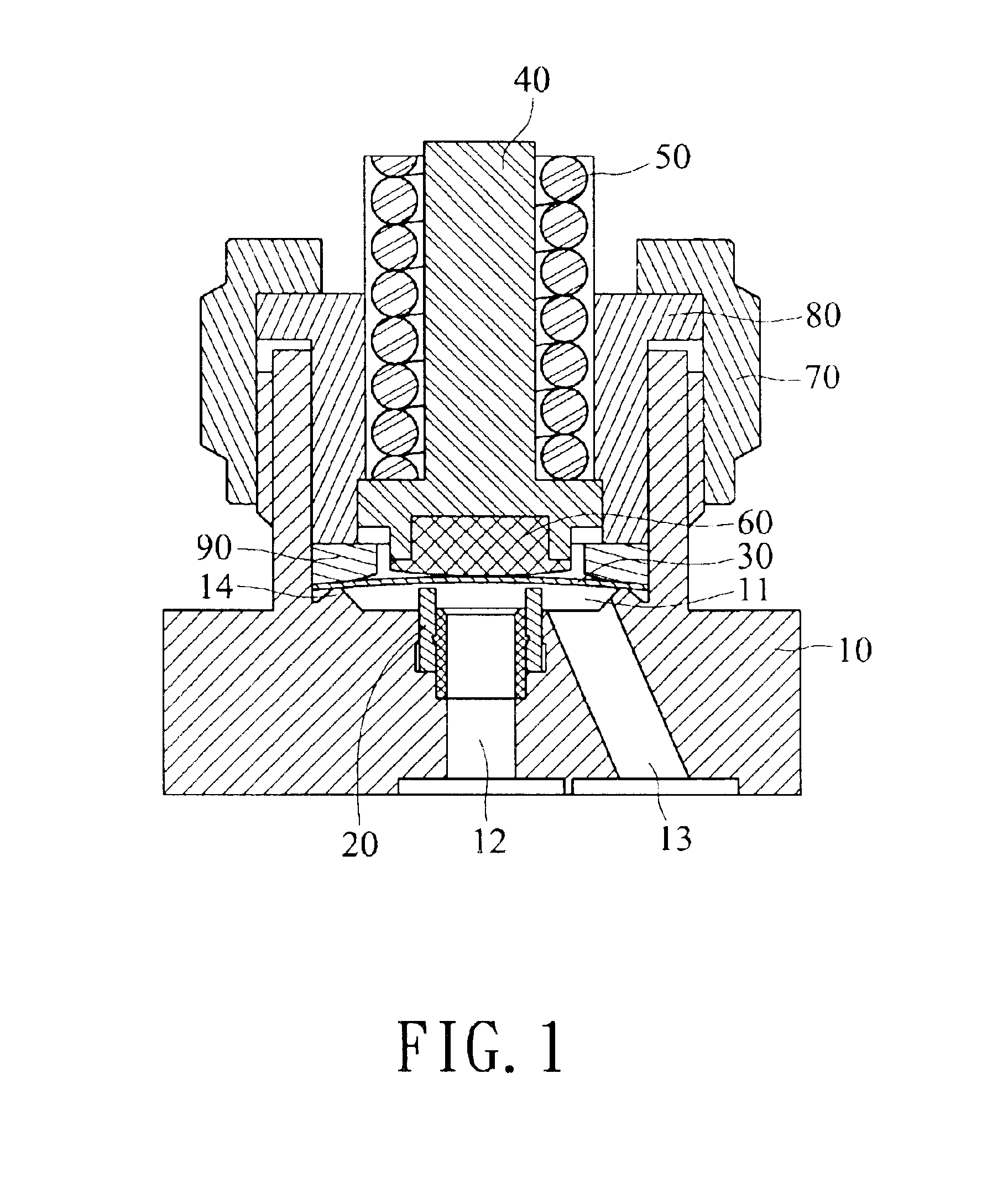
FIG 1 is a lateral view of the diaphragm valve in the invention and is provided with a valve body 10, inside of which is a chamber 11, the first flow channel 12 for air inflow and the second flow channel 13 for air outflow.

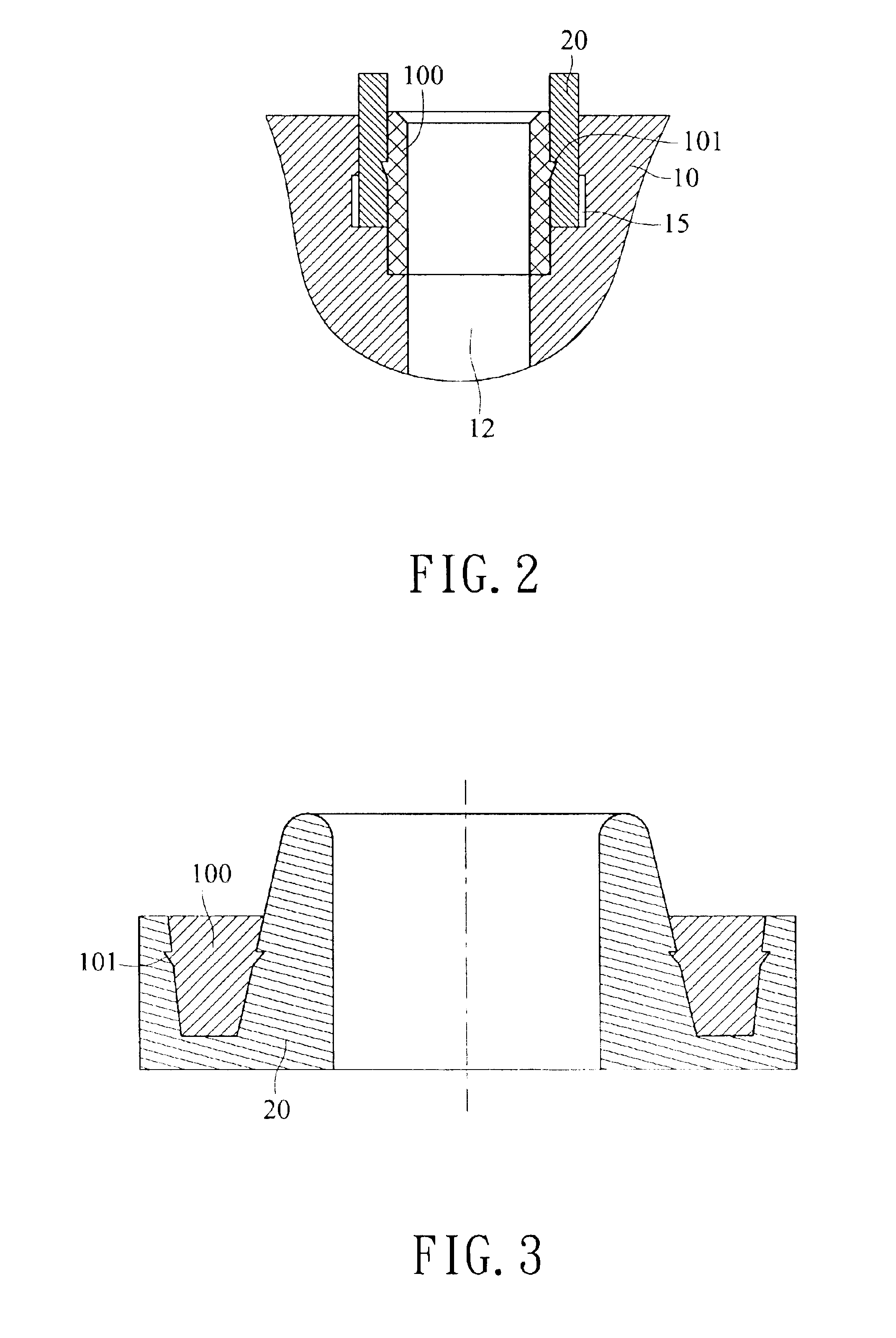
In the first flow channel 12, a non-metal valve base 20 is set near the chamber 11, and above it is the metal dish-type diaphragm set 30 controlling air inflow and outflow, which is made of springy metal.

When you want to block the air-inflow, move the stem 40 downward by controlling the spring 50 and pneumatic system interlocked with stem 40. The stem 40 will drive the presser 60 to press the metal dish-type diaphragm set 30 underneath, which will press against the non-metal valve base 20, thus blocking air inflow.

On the contrary, when you want air outflow, separate the presser 60 and metal dish-type diaphragm set 30 by controlling the spring 50 and the pneumatic system (not shown in figures), and when the metal dish-type diaphragm set 30 is free from downward pre...


PUM


Abstract

The diaphragm valve uses a metal dish-type diaphragm set to control the inflow and outflow of fluid. The metal dish-type diaphragm set is above an air flow channel to control the stem above the metal dish-type diaphragm set, and the air will be blocked by pressing the metal dish-type diaphragm to make it fit the metal valve base in the air flow channel; this non-metal valve base is fixed in the air flow channel by a fixed shrunk ring with a taper cross section, and the in-between metal diaphragm in the metal dish-type diaphragm set is annular in the center to reduce the metallic friction between metal diaphragms, to increase application times and to lower the leakage rate of the diaphragm valve.

Description

FIELD OF THE INVENTIONThe invention relates to a diaphragm valve, which uses a metal dish-type diaphragm set to control the inflow and outflow of fluid.BACKGROUND OF THE INVENTIONA “valve” is a functional unit with moveable switches, and used to control the flowing, pausing, flow quantity and pressure of fluid in pipelines. Its functions break into five parts: (1) a front-and a back part (2) an adjustment of the flow quantity (3) prevention of the countercurrent flow (4) the alteration of the flow direction and (5) pressure-control of fluid.For life-related tap water, gases in semiconductor plants and chemicals, food or products of petrifaction plants, valves are needed to adjust the flow quantity of a fluid, to control the flow rate and pressure or to control its fluid-acceptance as long as the fluid is conveyed by pipelines. Thus, we see that the valve is an indispensable part in the semiconductor industry, chemical industry and food industry.The internal surface of pipes, used to...

Claims


Application Information

Patent Timeline
IPC IPC(8): F16K7/12F16K7/16F16K1/42F16K1/32
CPCF16K1/425F16K7/16
Inventor LIN, CHUN-HUNGTSAI, CHEN-DERWU, CHIN-CHINGHO, JUNG-CHENWANG, HANN-TSONG
Owner IND TECH RES INST
Why Eureka
Try Eureka