Materials transport container

a technology for transporting containers and materials, applied in the direction of transportation items, monocoque constructions, vehicle bodies, etc., can solve the problems of high abrasion at the junction between the side walls and the floor surface of dump bodies, and achieve the effects of reducing the resistance to materials sliding, accelerating material sliding, and rapid raising and lowering

Inactive Publication Date: 2005-02-15
KOSTECKI GENE
View PDF17 Cites 50 Cited by
  • Summary
  • Abstract
  • Description
  • Claims
  • Application Information

AI Technical Summary

Benefits of technology

In a first aspect, but not necessarily the broadest or only aspect, the invention could be said to reside in a materials transport container having a floor and two opposed side walls and a front wall said walls extending upwardly from the floor, the container further having an unloading end (or rear end), the container supported to enable tilting for unloading of material from the unloading end, the container having a substantially continuous and smooth hard faced surface on an unloading portion of the floor adjacent the rear end, so as to enhance the sliding of material over the smooth hard faced surface, the hard facing is provided by a layer of hard surfacing alloy there being provided one or more arcuate surfaces bridging a junction between one or more of the front and side walls and the floor of the container to reduce hangup of material thereon.
The surface to be covered can be covered by a plurality of strips and this allows surfaces of various sizes and configurations to be covered without having to manufacture plates to conform to any specific size or shape.

Problems solved by technology

In addition to the above, in practice it is found that the junctions between the side walls and the floor surface of dump bodies are also subjected to a high degree of abrasion and form an area where two adhesive surfaces are angled to each other in such a way that material tends to hang up in the junctions when the body is tilted, and the material does not flow under the influence of gravity alone.

Method used


Image

  • Materials transport container
  • Materials transport container
  • Materials transport container

Examples


Embodiment Construction

Similar reference characters indicate corresponding parts throughout the several views of the drawings.

Dimensions of certain of the parts shown in the drawings may have been modified and / or exaggerated for the purposes of clarity or illustration.

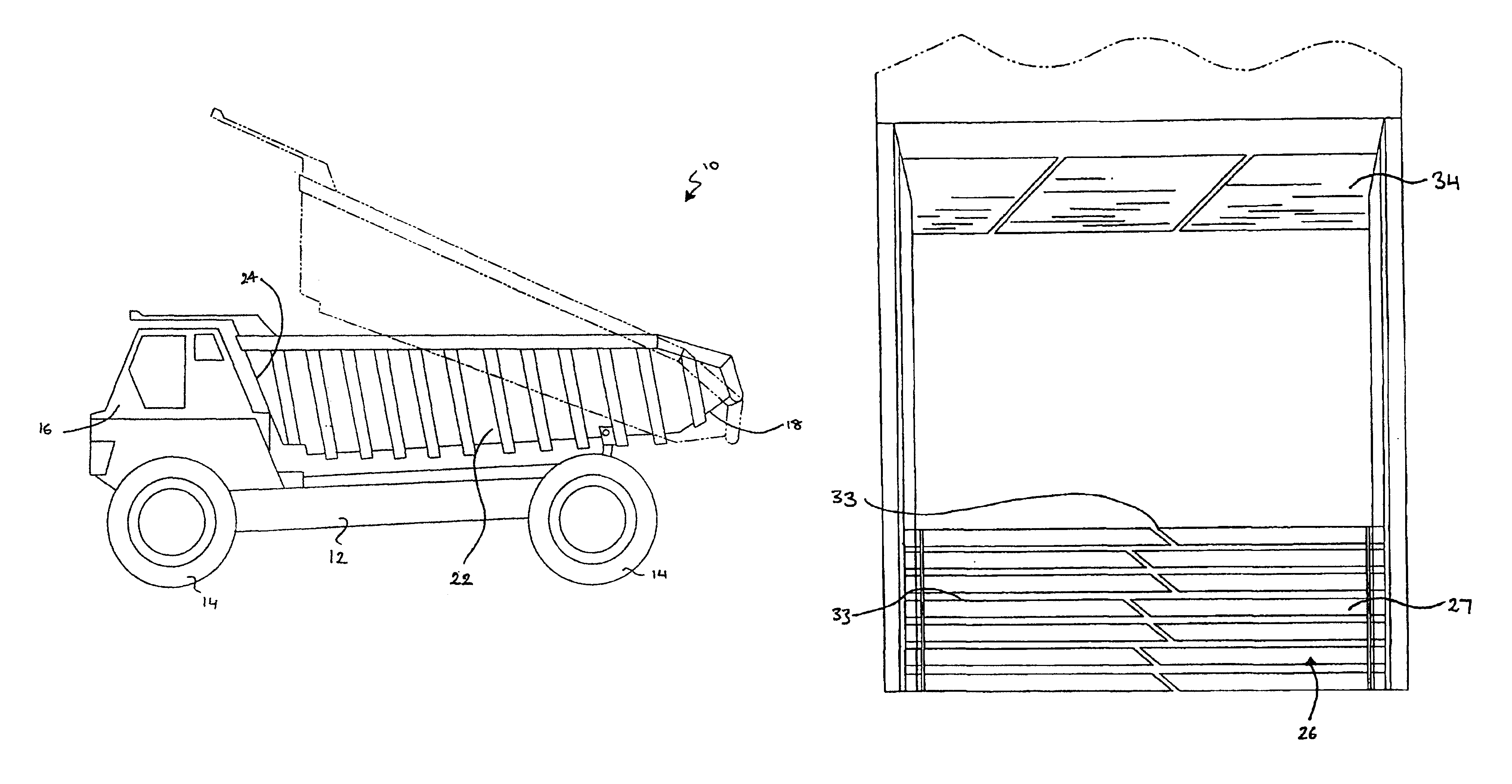
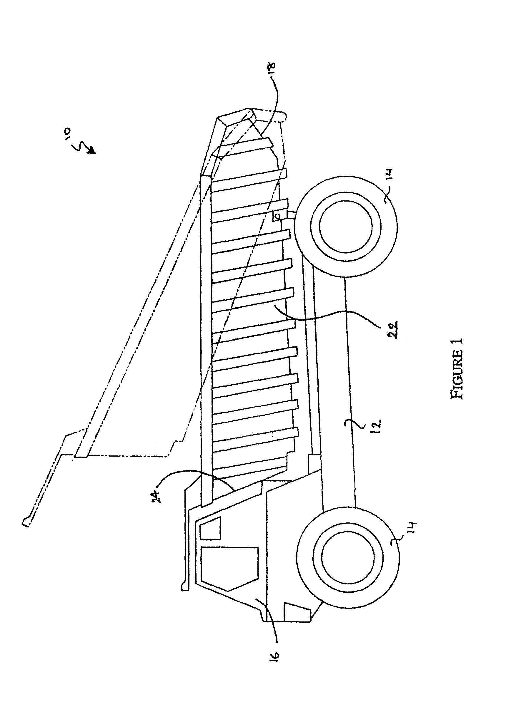
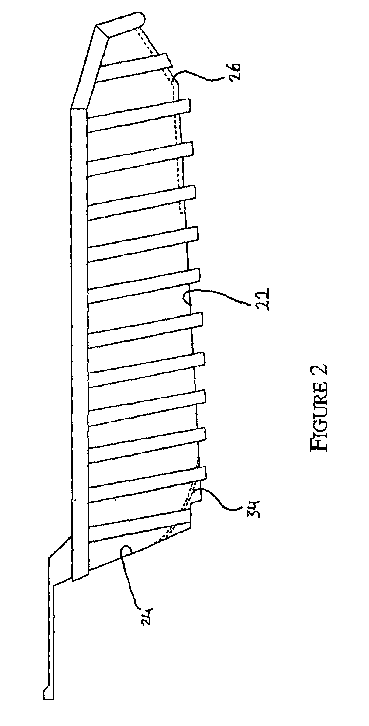
FIGS. 1 to 4 show a dump truck carrying a dump body into which material can be loaded for transport and then unloaded. Dump trucks of this type are typically used in the mining and construction industries and therefore the material to be transported can include soil, rocks, coal and the like.

The dump truck (10) is a self propelled vehicle and may be an off-highway vehicle that is used to carry tons of material in operations such as mining. Dump truck (10) includes a chassis (12) that is supported by wheels and tyres (14). The chassis (12) carries a cab (16) at a forward end and a box-like rigid load carrying dump body (18) at the back end. Whilst the illustrated embodiment shows a self propelled vehicle, the container of the present inventio...


PUM


Abstract

A materials transport container having a floor and two opposed upwardly extending side walls and a front wall. The container is supported to enable tilting for unloading of material from a rear end. The container has a substantially continuous and smooth hard faced surface on a rear portion of the floor adjacent the rear end to enhance sliding of its load over the smooth hard faced surface. Additionally arcuate surfaces bridging a junction between one or more of the front and side walls and the floor of the container to reduce hangup of material. The arcuate surfaces are smooth hard faced surfaces. The hard faced surfaces are provided by removable wear plates with gaps between then to allow flexion and ease of removal. It is found with use these hard faced wear plates become polished and greatly assist with the removal of material from the transport container.

Description

FIELD OF THE INVENTIONThe present invention relates to bulk materials transport containers, and in particular to bulk materials transport containers such as dump bodies of dump trucks or buckets of front end loaders that have improved flow characteristics of bulk materials across surfaces of the container upon unloading the container.BACKGROUND OF THE INVENTIONBulk materials transport containers such as dump bodies on dump trucks, buckets on front end loaders and the like are used in many industries for the transport of materials from one area to another. For example, in the mining industry dump trucks are used to transport mined materials from the mine site to a processing site. In the case of the mining industry, as well as many other industries, the material transported can have a hardness that is greater than the material from which the container is formed, which is typically steel. As a result, the load materials can be very abrasive and movement of the materials across interna...

Claims


Application Information

Patent Timeline
Patent Type & Authority Patents(United States)
IPC IPC(8): B62D33/02B60P1/04B60P1/28B60R13/01
CPCB60P1/286B62D33/02B60R13/01
Inventor KOSTECKI, GENE
Owner KOSTECKI GENE
Why Eureka
Try Eureka