
Amorphous non-intumescent inorganic fiber mat for low temperature exhaust gas treatment device

a technology of inorganic fiber and low temperature, applied in the direction of filtration separation, physical/chemical process catalysts, separation processes, etc., can solve the problems of high frequency of failure of catalytic converters, monolithic structures can be so fragile, and structures can be very fragile, and achieve the effect of providing resistance to slippage of the supporting elemen

Inactive Publication Date: 2005-02-15
UNIFRAX I LLC
View PDF17 Cites 106 Cited by
  • Summary
  • Abstract
  • Description
  • Claims
  • Application Information

AI Technical Summary

Benefits of technology

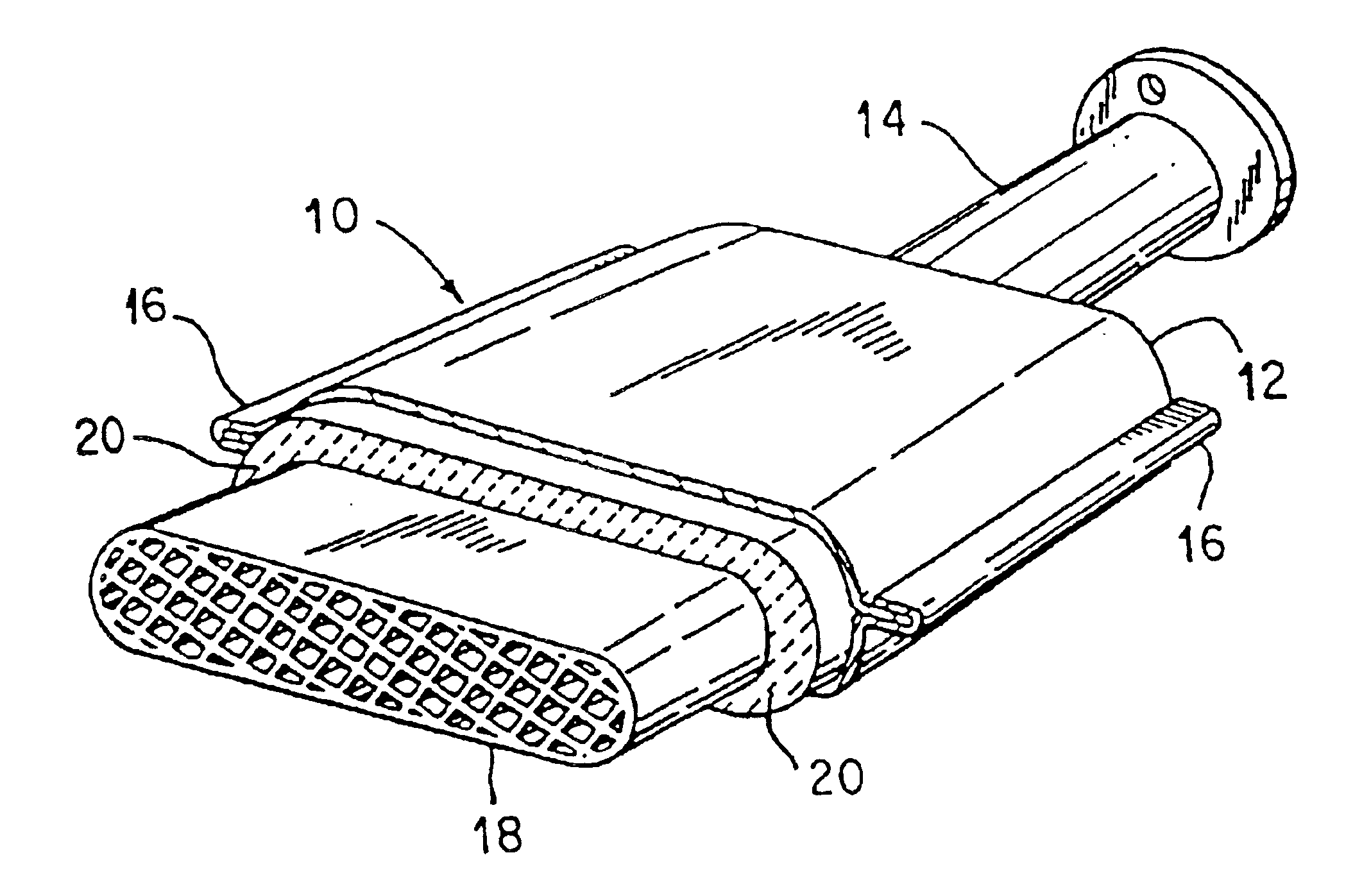
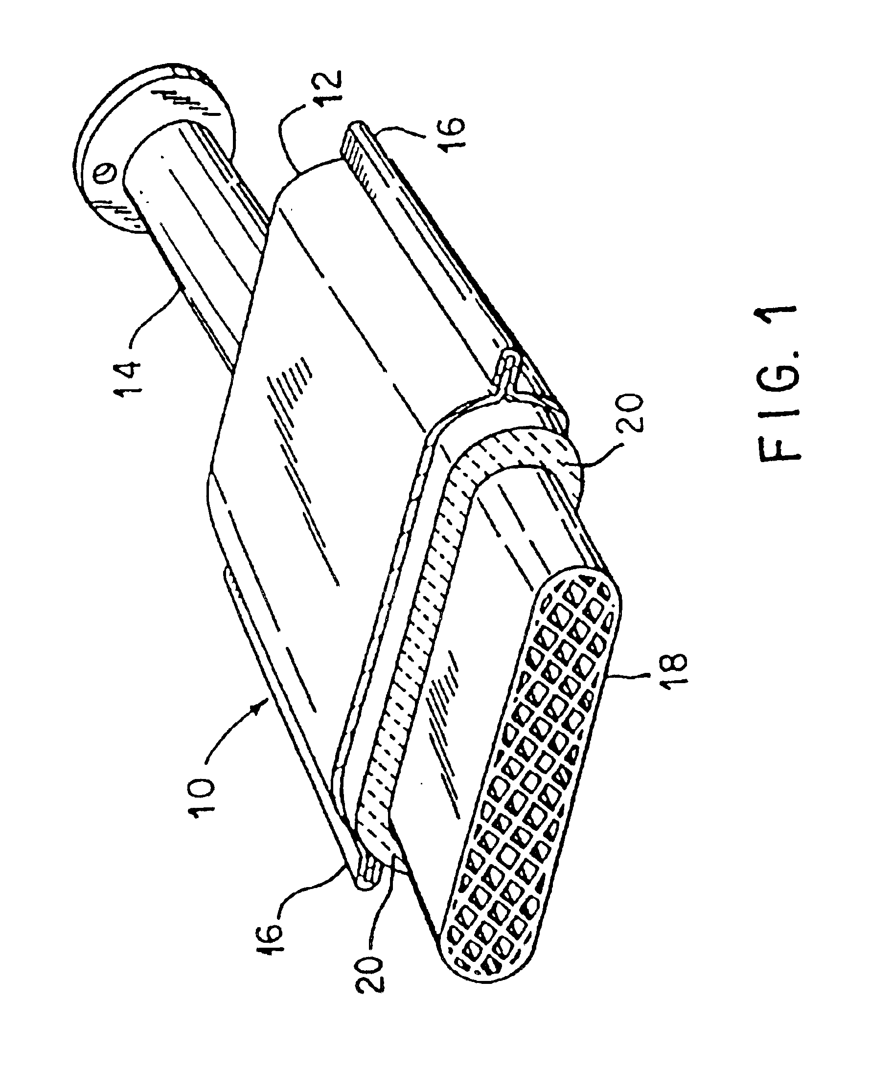
The present invention provides a non-intumescent mat for use in low temperature exhaust gas treatment devices. The mat is made of high temperature resistant, amorphous, inorganic fibers that have a low modulus and small diameter. The mat can optionally include a binder and provides support for fragile structures at temperatures up to 350°C. The invention also provides an exhaust gas treatment device with a fragile support structure and a support element made of the non-intumescent mat. The support element is designed to prevent slippage in the housing at a force of at least 60 times the acceleration of gravity.

Problems solved by technology

However, as noted hereinabove, these structures can be, and oftentimes are, very fragile.
In fact, these monolithic structures can be so fragile that small shock loads or stresses are often sufficient to crack or crush them.
In low temperature catalytic converter applications, such as turbocharged direct injection (TDI) diesel powered vehicles, the exhaust temperature is typically about 150° C., and may never exceed 300° C. It has been observed in the field that catalytic converters, that are assembled with typical intumescent mats, fail with an unexpectedly high frequency.
One reason for these failures is that the exhaust temperature is too low to expand the intumescent, typically vermiculite, particles.
When subsequently used in the low temperature TDI application, the mats fail to provide sufficient pressure against the fragile structure and thus fail.
A second reason for these failures is that organic binder systems used in the intumescent mat products degrade and cause a loss in the holding force.
Historically, these products have been dry layed without the addition of organic binder; as a result, the thickness of these products is typically greater than 18 mm making them difficult to install in converters, as described in the patents referenced above.
Further, the cost of these products has been prohibitively high as compared to intumescent mats.
All of the binders referenced in this patent, however, yield a mat with lower performance in the 150°-300° C. operating temperature range of a TDI diesel converter.
Upon thermal cycling of the converter, the hardened mat is no longer capable of maintaining adequate holding force on the fragile structure and failure results.

Method used


Image

  • Amorphous non-intumescent inorganic fiber mat for low temperature exhaust gas treatment device
  • Amorphous non-intumescent inorganic fiber mat for low temperature exhaust gas treatment device
  • Amorphous non-intumescent inorganic fiber mat for low temperature exhaust gas treatment device

Examples


example 2

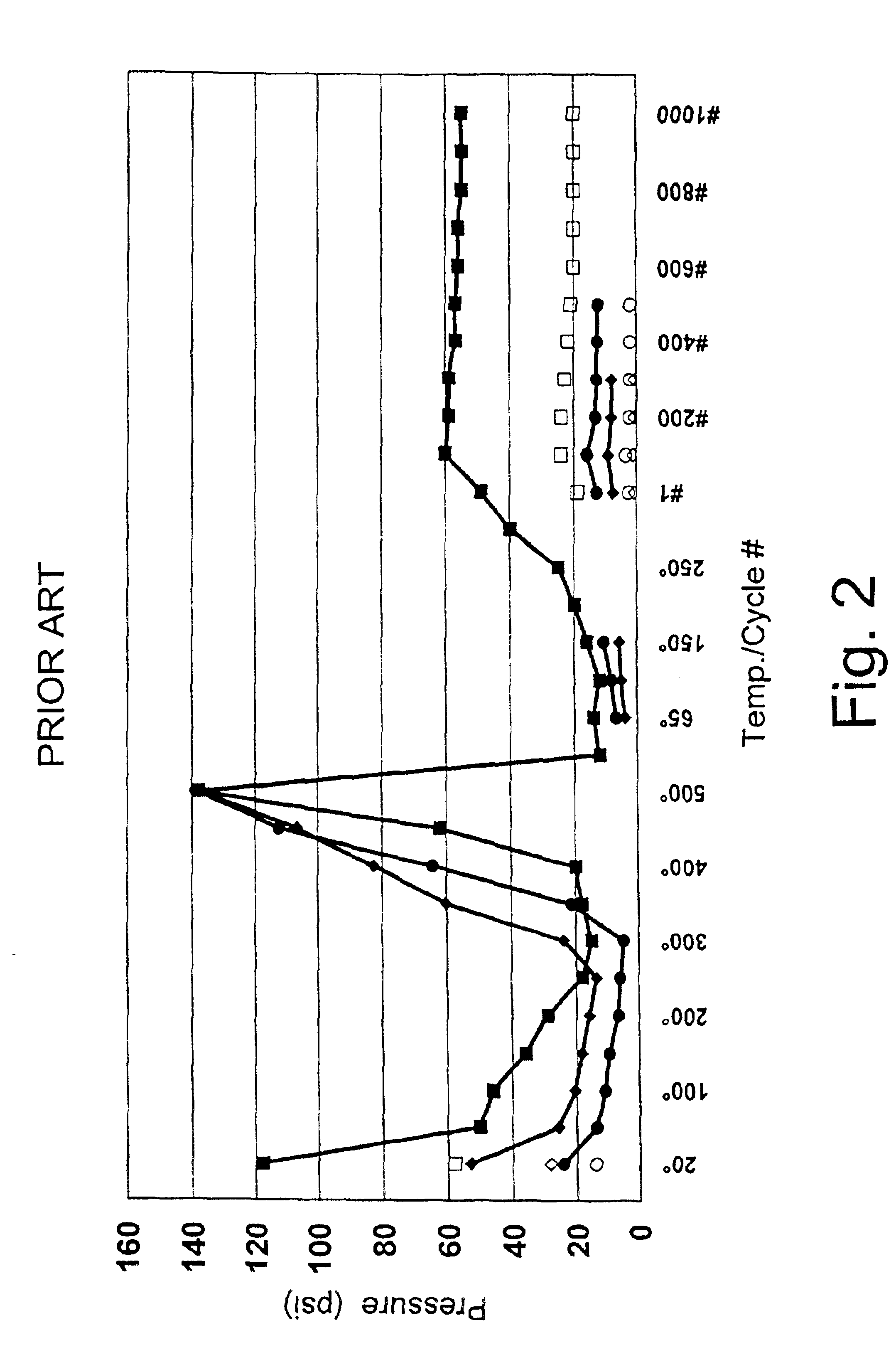
Simulation of a TDI diesel converter was performed by cycle testing mats at 300° C. for 1000 cycles between a gap of about 3.0 to about 3.1 mm. The results are shown in FIG. 4. The samples were a 1550 g / m2 of a competitive dry layed, needle punched ceramic (about 50% alumina / 50% silica) fiber blanket, such as ULTRAFELT® manufactured by Thermal Ceramics, Augusta, Ga., (shown by an open diamond), and a 1600 g / m2 mat of the present invention prepared with a 50% alumina / 50% silica fiber with no binder (shown by a triangle); a silicone binder (shown by a solid square); and an acrylic binder that was not burned out prior to installation (shown by an solid circle).

The mat with the silicone binder comprised 92% of an amorphous fiber comprising 50% Al2O3 and about 50% SiO2 with a fiber index of 72% and 8% of a silicone latex binder (DOW CORNING #85 silicone latex from Dow Corning, Inc. Midland, Mich.). The resulting mat had a basis weight of 1600 g / m2 and was 7 mm thick. As shown in FIG. 4, ...

example 3

Testing in a Catalytic Converter

A 4.66″ diameter converter was assembled with comparative mats and tested in a hot shake test at 300° C. with an acceleration of 60 times gravity (60 g's). The converter with a traditional intumescent mat, consisting of approximately 55% unexpanded vermiculite, 37% ceramic fiber, and 8% acrylic latex binder, such as INTERAM® TYPE-100 and INTERAM® TYPE-200, lost its holding force and the fragile structure slipped within the shell in less than 50 hours.

A mat of the present invention, made with amorphous alumina / silica fiber and an acrylic latex binder which had been burned out prior to installation in the converter, was run in the hot shake test at 300° C. with an acceleration of 60 g and performed for 100 hours without failure. Upon inspection after testing, the fragile structure was found to be firmly mounted in the shell, with no relative axial movement. The mat was also found to be undamaged by gas erosion or other visible degradation.

A mat of the p...


PUM

PropertyMeasurementUnit
temperatureaaaaaaaaaa
Young's Modulusaaaaaaaaaa

Abstract

A non-intumescent mat for providing a support structure for low temperature fragile structures in exhaust gas treatment devices, such as catalytic converters, diesel particulate traps, and like, comprising amorphous inorganic fibers. The fibers have Young's Modulus of less than about 20×106 psi and a geometric mean diameter less than about 5 μm. The mat is adapted to provide a holding force of at least 15 psi throughout an average mat temperature range from ambient temperature up to at least about 350° C. The amorphous inorganic fibers are preferably melt formed fibers comprising the fiberization product of a melt comprising alumina / silica.

Description

FIELD OF THE INVENTIONThe present invention is directed to a mat functioning as a support element for fragile structures in exhaust gas treatment devices, such as catalytic converters, diesel particulate traps, and the like, for the treatment of exhaust gases. More particularly, the present invention is directed to an amorphous, non-intumescent inorganic fiber mat as a support element for low temperature exhaust gas treatment devices.BACKGROUND OF THE INVENTIONCatalytic converter assemblies for treating exhaust gases of automotive and diesel engines contain a fragile structure, such as a catalyst support structure, for holding the catalyst, used to effect the oxidation of carbon monoxide and hydrocarbons and the reduction of oxides of nitrogen, the fragile structure being mounted within a metal housing. The fragile structure is preferably made of a frangible material, such as a monolithic structure formed of metal or a brittle, fireproof ceramic material such as aluminum oxide, sili...

Claims


Application Information

Patent Timeline
Patent Type & Authority Patents(United States)
IPC IPC(8): B01D53/88B01D53/94F01N3/28F01N3/021B01D39/20B01D39/14D04H1/4218D04H1/46
CPCB01D53/885B01D53/9454D04H1/4218D04H1/46Y02T10/22F01N3/2853Y10S428/92Y02T10/12B01D53/34
Inventor TENEYCK, JOHN D.
Owner UNIFRAX I LLC
Learn More