Particle beam system having a mirror corrector

Inactive Publication Date: 2005-02-15
LEO ELEKTRONENMIKROSKOPIE
View PDF20 Cites 23 Cited by
  • Summary
  • Abstract
  • Description
  • Claims
  • Application Information

AI Technical Summary

Benefits of technology

The total system with the mirror corrector is preferably so operated that, simultaneously, the chromatic and aperture aberrations of the total imaging sy

Problems solved by technology

However, in this operating mode, a dispersion in the image occurs which must be compensated after a two-time passthrough through the deflector.
The concave outer surfaces of the

Method used


Image

  • Particle beam system having a mirror corrector
  • Particle beam system having a mirror corrector
  • Particle beam system having a mirror corrector

Examples


Embodiment Construction

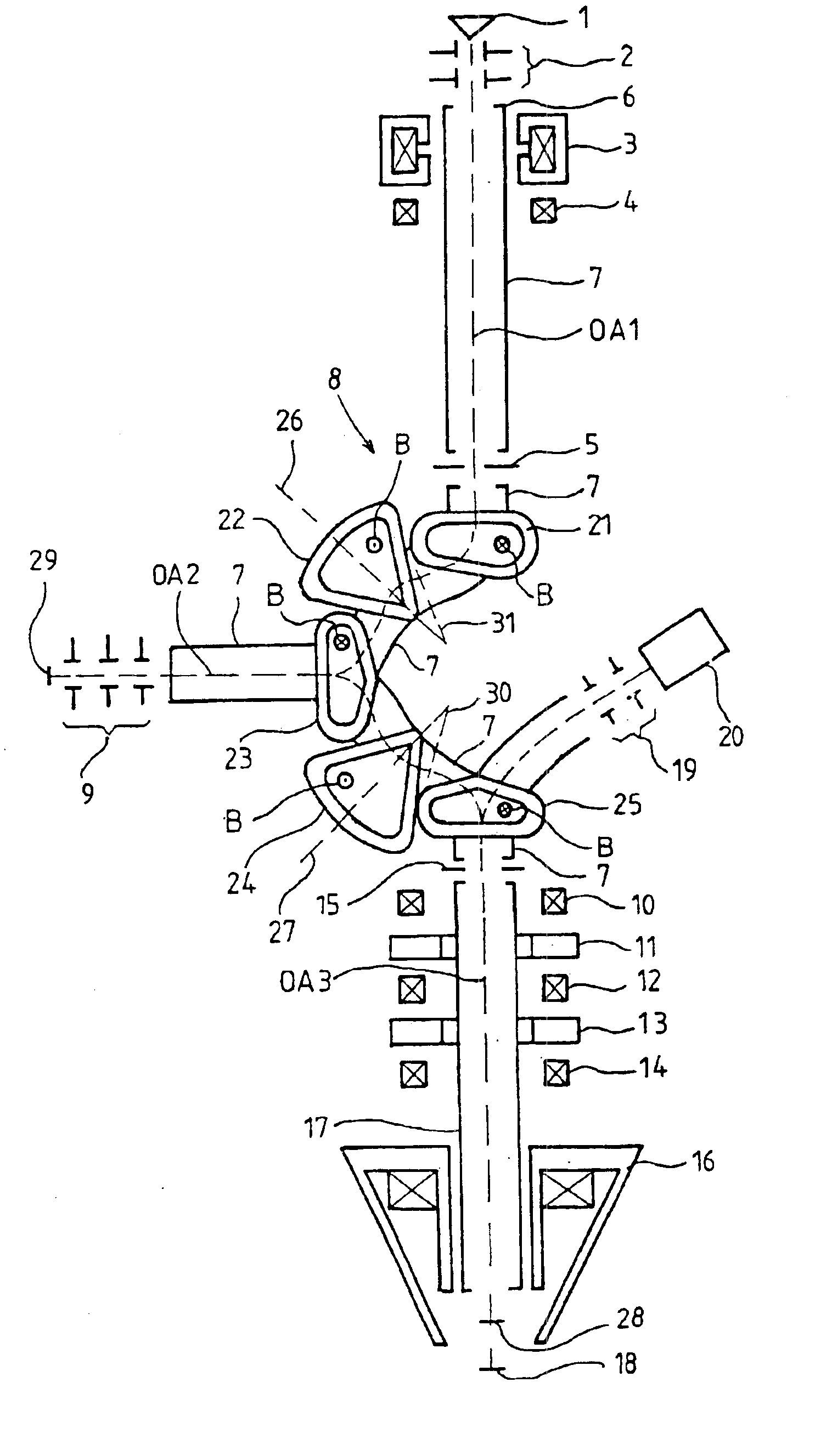
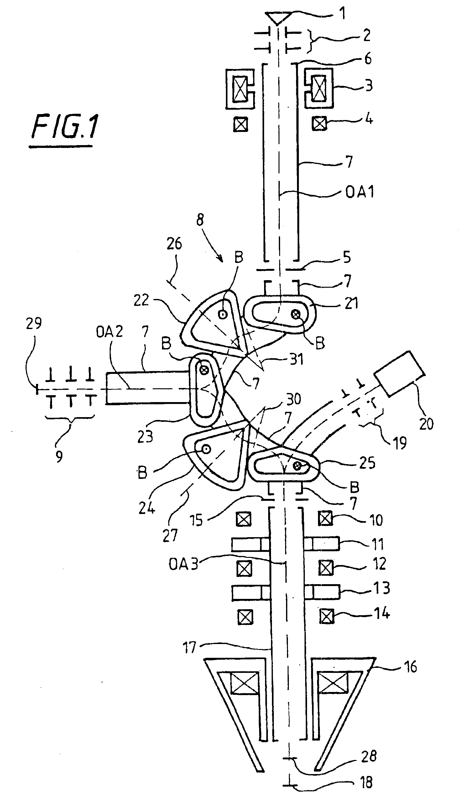
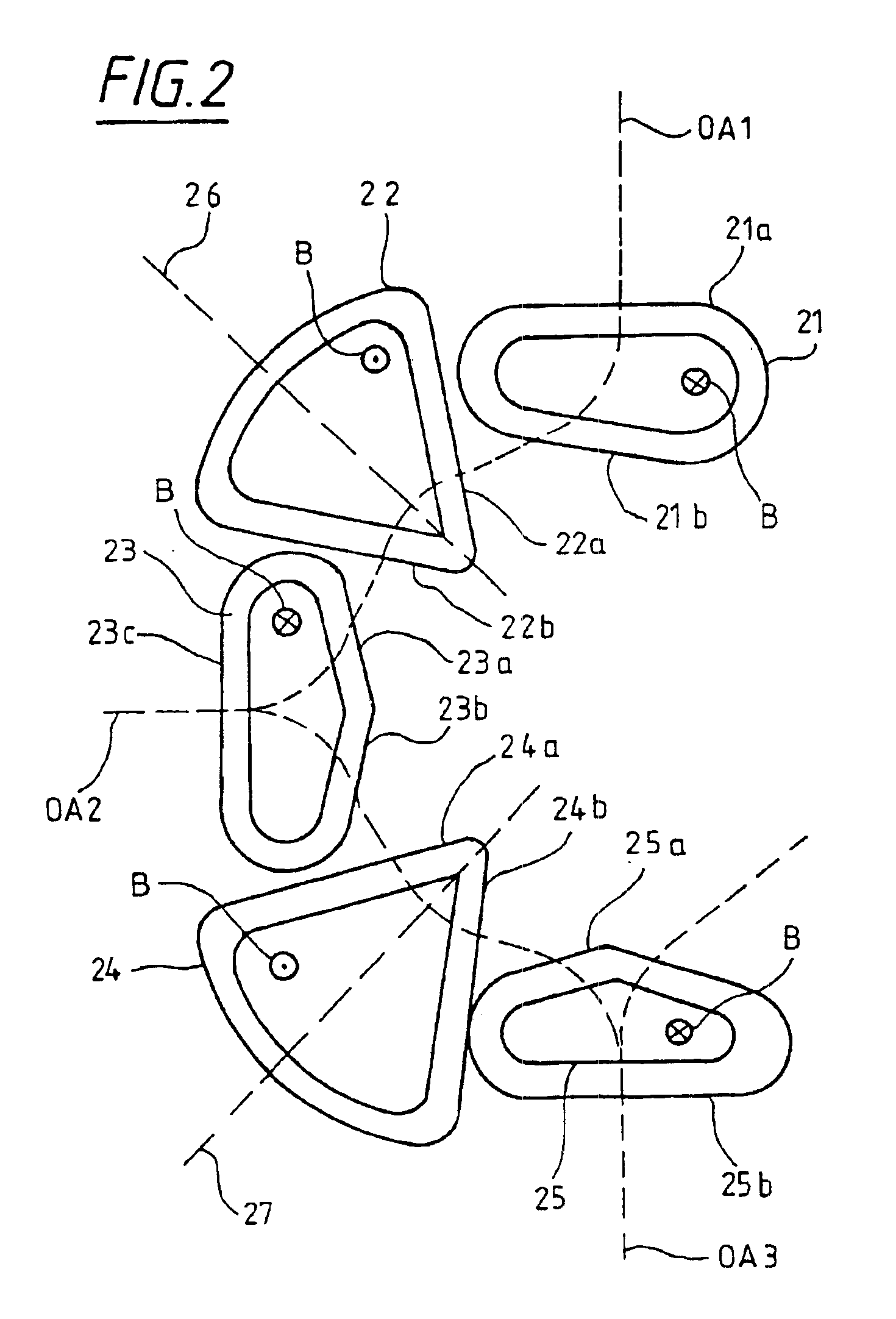
The raster electron microscope shown in FIG. 1 includes a particle source 1 having a beam accelerator 2 downstream of the particle source 1. After a run-through through the beam accelerator 2, the particles are accelerated to the potential of the beam-guiding tube 6. A magnetic condenser lens 3 and a stigmator 4 following the condenser lens 3 are provided in the region of the beam-guiding tube 6 which, for example, lies at a potential of 10 kV relative to the particle source 1. The condenser lens 3 functions to expand the beam in the beam tube following below. A first electrostatic immersion lens 5 follows the stigmator 4 via which immersion lens the electrons are further accelerated to a higher kinetic energy, namely, the kinetic energy of the inner beam-guide tube 7. In the region of the inner beam-guide tube 7, approximately at the center of the raster electron microscope, the beam deflector is mounted with the magnetic sectors 21 to 25. The beam deflector operates as a particle-...


PUM


Abstract

The invention relates to a particle beam system comprising a particle source (1), a mirror corrector (9, 21 to 25), and an objective lens (16). The mirror corrector comprises an electrostatic mirror (9) and a magnetic beam deflector (21, 22, 23, 24, 25), which is arranged between the particle source (1) and the electrostatic mirror (9) as well as between the electrostatic mirror (9) and the objective lens (16). The magnetic beam deflector (21, 22, 23, 24, 25) is free from dispersion for each single pass. The magnetic beam deflector (21, 22, 23, 24, 25) also comprises quadrupoles and/or quadrupole components, which are provided in such a manner that a maximum of two planes, which are conjugated with regard to the diffraction plane (28) of the objective lens (16), occur on the entire path length between the first outlet from the magnetic beam deflector (21, 22, 23, 24, 25) and from the objective lens (16).

Description

BACKGROUND OF THE INVENTIONThe invention relates to a particle beam system having a mirror corrector. A system of this kind is, for example, disclosed in U.S. Pat. No. 5,319,207. The mirror corrector functions in such systems to correct the geometric and energy-dependent aberrations of the particle-optical components contained in the system.Mirror correctors include a magnetic beam deflector in addition to an electrostatic mirror. Such a beam deflector functions, to a certain extent, as a switch for the particle beams in order to, on the one hand, deflect the particle beam exiting from a source to the electrostatic mirror and to deflect the particle beam, which is reflected at the electrostatic mirror, to the downstream imaging optics.So that the beam deflector, being a non-rotational-symmetrical electron-optical component does not itself generate aberrations of the second order, it is known from U.S. Pat. No. 5,319,207 to symmetrically configure corresponding beam deflectors so tha...

Claims


Application Information

Patent Timeline
IPC IPC(8): H01J37/28H01J37/153
CPCH01J37/153
Inventor ROSE, HARALDPREIKSZAS, DIRKHARTEL, PETER
Owner LEO ELEKTRONENMIKROSKOPIE
Why Eureka
Try Eureka