Enhancements for adhesive attachment of piezoelectric motor elements to a disk drive suspension

a piezoelectric motor and adhesive technology, applied in piezoelectric/electrostrictive/magnetostrictive devices, piezoelectric/electrostriction/magnetostriction machines, electrical apparatus, etc., can solve the problems of increasing the number of rejectable fillets, increasing the number of incomplete bond pads, and increasing the number of fillets. , to achieve the effect of improving the filling of adhesive, improving the bond strength, and improving the thickness

Inactive Publication Date: 2005-02-15
HUTCHINSON TECH
View PDF17 Cites 68 Cited by
  • Summary
  • Abstract
  • Description
  • Claims
  • Application Information

AI Technical Summary

Benefits of technology

The present invention is an improvement for use with the adhesive attachment of piezoelectric elements used as linear motors on disk drive suspensions. The improvement is a relief under, partially under, or adjacent the piezoelectric transducer which helps control the adhesive by limiting or influencing adhesive travel or flow and simultaneously preventing excessive fillet height adjacent the PZT, while (also simultaneously) providing for sufficient adhesive bond area between the PZT and the supporting substrate to improve bond strength. Features of the invention in the substrate, which is normally stainless steel (SST), include one or more recesses which are partially etched, through etched, coined, laser cut, or otherwise made in the motor attachment area of the substrate.
The preferred configuration is one in which the adhesive attach enhancement features may border up to three sides of each end of a PZT motor with sufficient width extending laterally outside and away from the motor to either limit the adhesive travel or allow excess adhesive to be drawn away from the motor. It may also have features or topography extending towards the corners of the motor. The substrate topography may be either recessed in relation to the surrounding area or include a raised portion in the substrate recess to encourage better filling of adhesive into the corners of the bond pad area of the PZT. In the practice of the present invention, it is preferred that there be sufficient area under the motor bond region that is not recessed to create an adhesive cushion that helps provide for an adequate bond line thickness. This thickness may be enhanced by including conductive particles in adhesive or by including controlled-size non-conductive particles added to the adhesive for this purpose. The exact shapes of the raised and recessed areas can be varied, depending on the improvements required.
The present invention provides the following additional improvements:1. Added adhesive joint strength. The mix of recessed and non-recessed areas provides a better mechanical bond for the adhesive to the SST. In suspensions without the adhesive attach enhancement features of the present invention, the observed failure mode is at the SST to adhesive interface. With recessed control features of the present invention, the failure plane remains the same at the un-etched areas but the failure mode at the recessed areas is changed to one within the adhesive. This provides opportunities to increase the strength of the joint by increasing the adhesive's internal strength.2. Complete bond pad area coverage. It has been observed that the motor attach adhesive bond's strength is diminished when the bond pad area is not completely filled with adhesive. Using the adhesive control features of the present invention allows enhanced movement of the uncured adhesive into the corners of the bond area thus helping to maximize the coverage of adhesive in the bond area.3. Control of adhesive fillets. The adhesive in an un-etched pad area tends to make a fillet going up the sides of the PZT mo...

Problems solved by technology

These fillets can short out the motor if they contain conductive particles and extend up to the top conductive surface.
As the adhesive volume is increased to ensure a complete bond pad, the number of rejectable fillets are also in danger of increasing.
When the height of the adhesive fillets is lowered by decreasing the adhesive ...

Method used


Image

  • Enhancements for adhesive attachment of piezoelectric motor elements to a disk drive suspension
  • Enhancements for adhesive attachment of piezoelectric motor elements to a disk drive suspension
  • Enhancements for adhesive attachment of piezoelectric motor elements to a disk drive suspension

Examples


Embodiment Construction

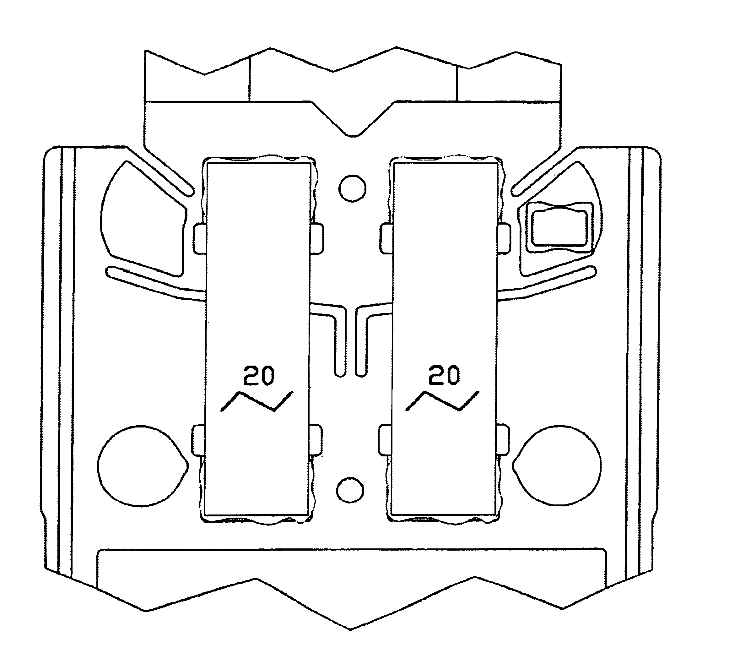
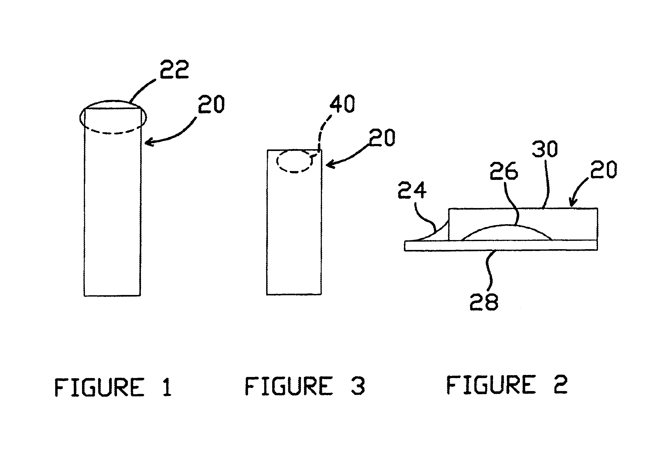
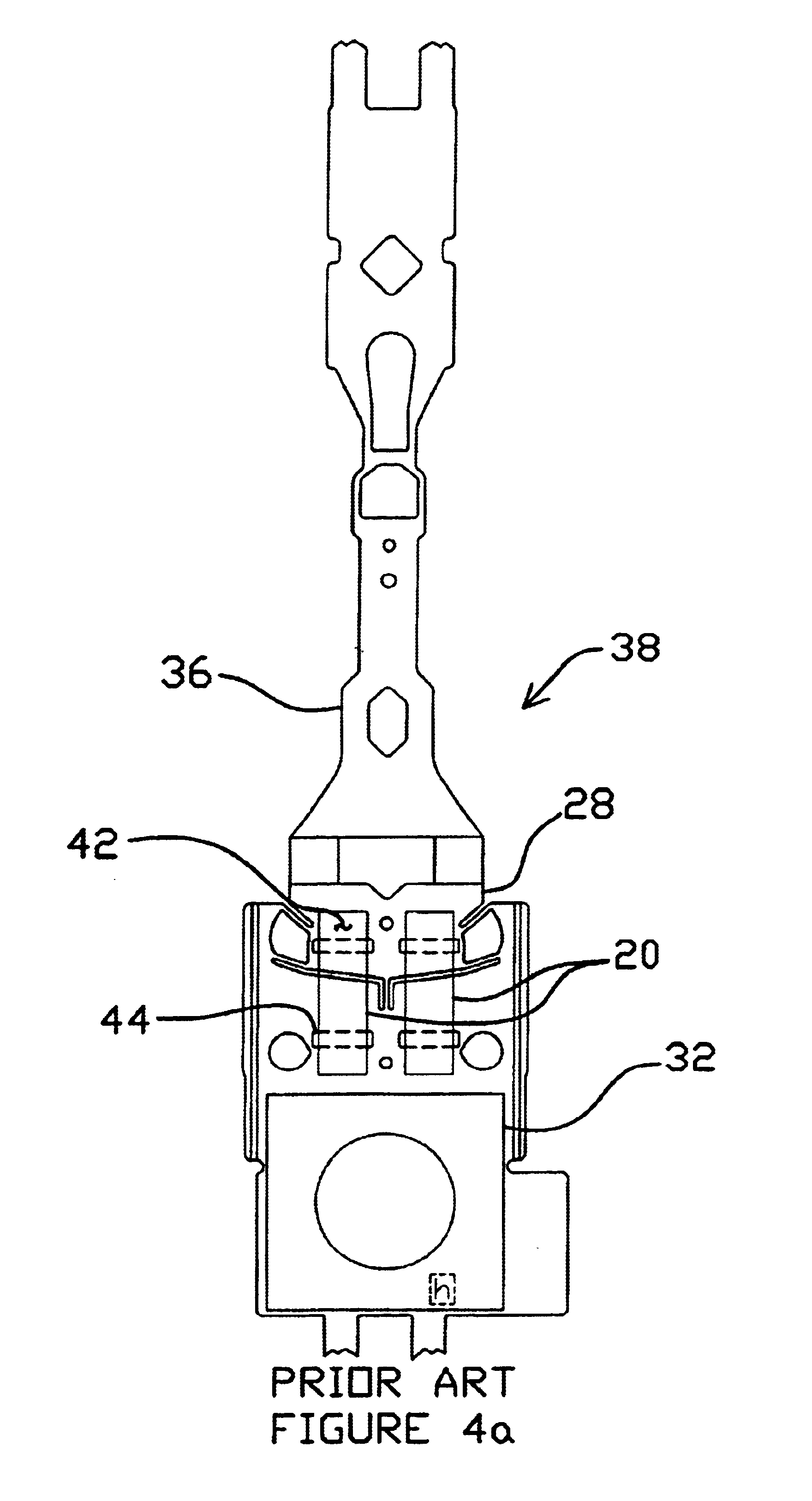
Referring to FIGS. 1, 2 and 3, the drawings show possible extremes of adhesive dot size and shape that can occur without adhesive attachment enhancements. FIG. 1 is a simplified top view of a PZT 20 which shows a large adhesive volume 22 that spreads out on the stainless steel suspension 28. This causes large adhesive fillets 24, 26 as shown in FIG. 2, which is a side view of the PZT and adhesive of FIG. 1. These fillets make the PZT to stainless joint stronger but if they are large enough, they can short the stainless steel 28 to the plated conducting top surface 30 of the PZT 20. This shorting problem causes the motor 20 to become inoperative. Referring now also to FIG. 4c, if the adhesive 34 spreads from the motor 20 all the way to a base plate 32, the relative movement of the base plate 32 to the suspension 28 could cause adhesive particles to be flaked off, resulting in contamination in the drive. The load beam 36 (formed of a load beam blank 38) of the suspension 28 is essenti...


PUM


Abstract

Adhesive attachment features for bonding piezoelectric motors to a load beam substrate. The attachment features have one or more reliefs under or partially under or adjacent to a piezoelectric transducer to control the flow of adhesive by limiting or influencing adhesive travel or flow and simultaneously preventing excessive adhesive fillet height adjacent the piezoelectric motor while simultaneously providing for improved bond strength between the piezoelectric element and the load beam.

Description

FIELD OF THE INVENTIONThe present invention relates to the field of disk drive suspensions having one or more piezoelectric transducers (PZT) attached to a substrate, typically made of stainless steel, arranged to operate as a limited range linear motor to position a distal end of the suspension laterally as desired.BACKGROUND OF THE INVENTIONThe prior art includes a non-etched area with one adhesive control feature in the form of a recessed line in the substrate located at the inner border of a bond pad area at each end of the piezoelectric transducer or motor to help prevent adhesive from wicking along the bottom surface of the motor beyond the bond pad area towards the center of the motor.SUMMARY OF THE INVENTIONThe present invention is an improvement for use with the adhesive attachment of piezoelectric elements used as linear motors on disk drive suspensions. The improvement is a relief under, partially under, or adjacent the piezoelectric transducer which helps control the adh...

Claims


Application Information

Patent Timeline
IPC IPC(8): H01L41/00H01L41/053
CPCH01L41/053H10N30/073
Inventor HOUK, GALEN D.SCHONES, THOMAS A.PETERSON, TONY S.
Owner HUTCHINSON TECH
Why Eureka
Try Eureka