
Method and apparatus for acquiring a frequency without a reference clock

a clock signal and frequency technology, applied in the field of data communication, can solve the problems of adding cost and design complexity to the system in which a clock and data recovery circuit resides

Inactive Publication Date: 2005-02-15
SKYWORKS SOLUTIONS INC
View PDF22 Cites 39 Cited by
  • Summary
  • Abstract
  • Description
  • Claims
  • Application Information

AI Technical Summary

Benefits of technology

Accordingly, a method and apparatus is provided for acquiring a frequency without using a reference clock. In one embodiment, a method is provided for acquiring a clock embedded in an input data stream, by varying an output of a variable oscillator until transitions of the input data stream occurring in a predefined phase zone of a sample clock sampling the input data stream occur at an acceptable rate. The acceptable rate is determined according to a number of evaluation intervals having one or more transitions occurring in the predefined phase zone.
In another embodiment, a method for reference-less frequency acquisition includes detecting whether transitions of the input data stream fall into a predetermined portion of a sample clock period of a sample clock utilized in a phase detector to sample the input data stream and evaluating whether a phase-locked loop (PLL) has acquired the timing of the input data stream according to the occurrence of transitio

Problems solved by technology

The requirement for a reference clock (generally differential) adds both cost and design complexity to the system in which a clock and data recovery circuit resides.

Method used


Image

  • Method and apparatus for acquiring a frequency without a reference clock
  • Method and apparatus for acquiring a frequency without a reference clock
  • Method and apparatus for acquiring a frequency without a reference clock

Examples


Embodiment Construction

)

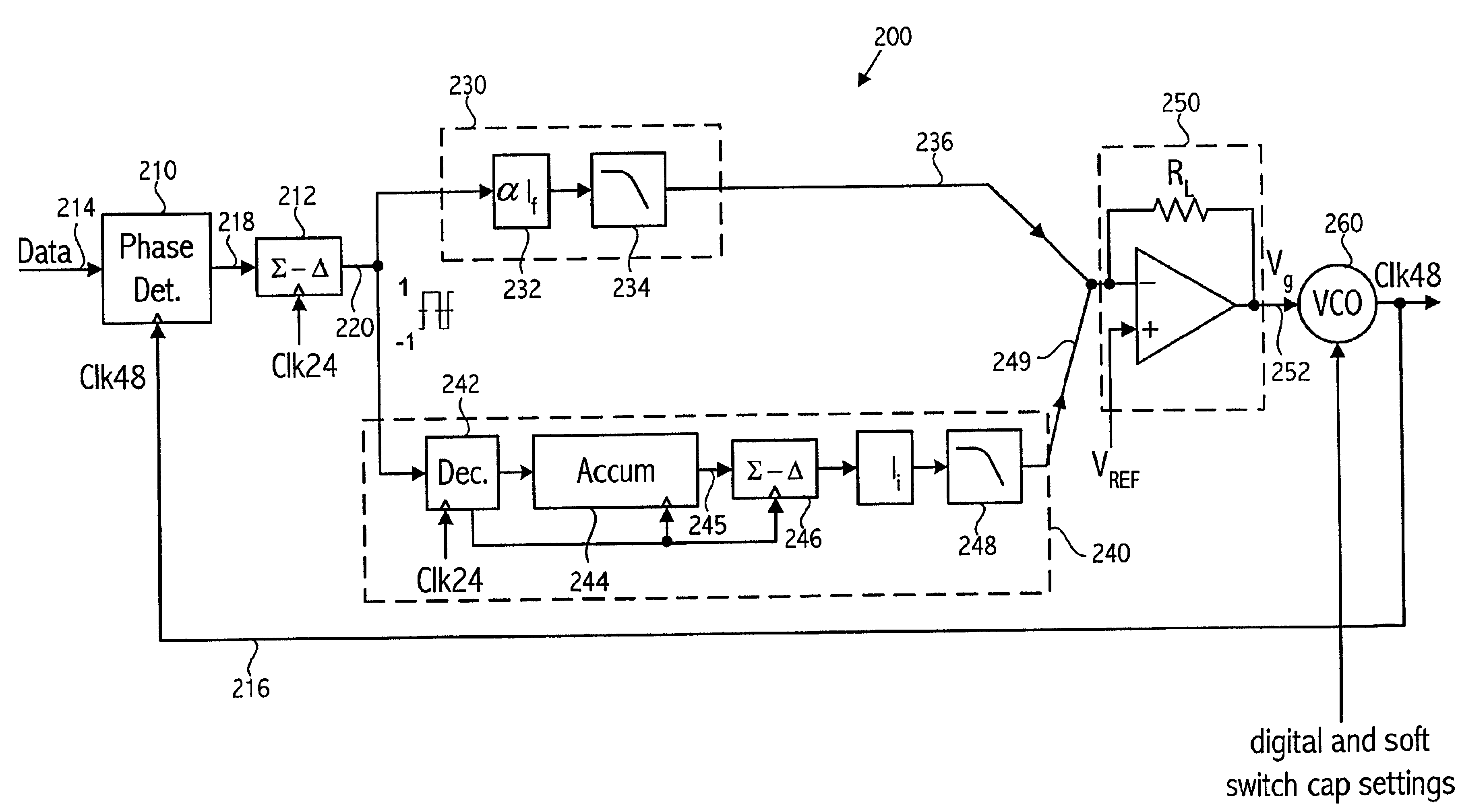
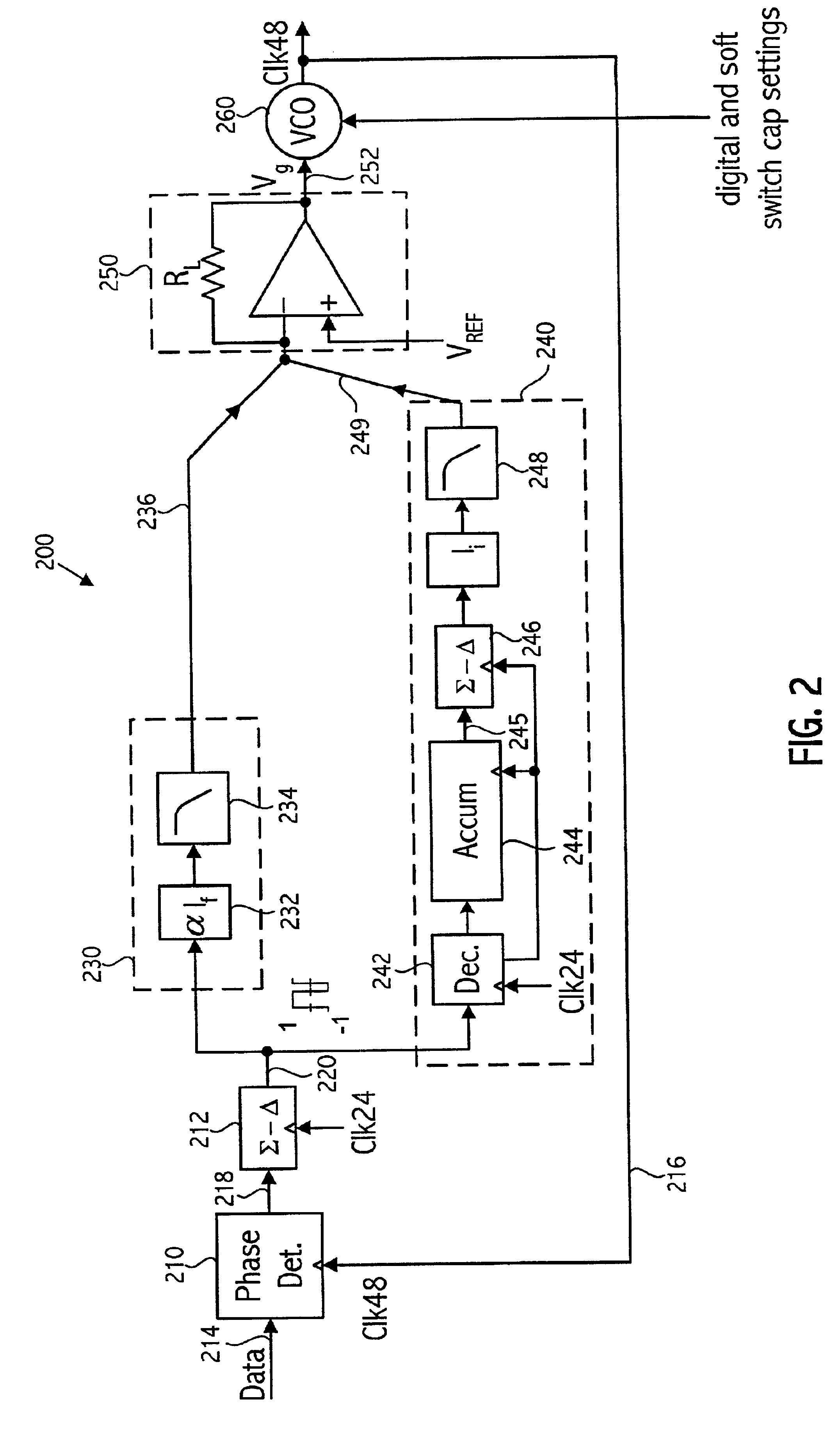
Referring to FIG. 2, a clock and data recovery architecture 200 that can be m utilized in conjunction with the present invention is illustrated. As seen in FIG. 2, a phase detector 210, an augmented version of which is described further herein, is followed by a delta-sigma modulator 212. The phase detector 210 compares the phase of the input data signal conveyed on node 214 to the phase of the recovered clock signal conveyed on node 216, and generates a pulse width modulated error signal waveform. In this example, the error signal is a current waveform flowing into or out of node 218. The delta-sigma modulator 212 then converts the pulse width modulated error signal into a discrete-time and discrete-amplitude digital output signal, in this example generating a one-bit digital output on its output node 220.

As shown in greater detail in FIG. 3 in one embodiment, the delta-sigma modulator 212 includes a modest-sized (e.g., having a typical value of 2-3 pF) integrating capacitor 222 co...


PUM


Abstract

A clock and data recovery system acquires a clock embedded in an input data stream by detecting the occurrence of transitions in the input data stream falling into a predetermined phase zone of a sample clock used to sample the input data stream. A control circuit counts how many evaluation intervals have at least one transition in the predetermined phase zone. The control circuit determines if lock is achieved according to the count. If it is determined that lock is not achieved, an output of a variable oscillator circuit used in the clock recovery operation is adjusted until the number of evaluation intervals having one or more transitions in the predetermined phase zone is below a level indicating lock.

Description

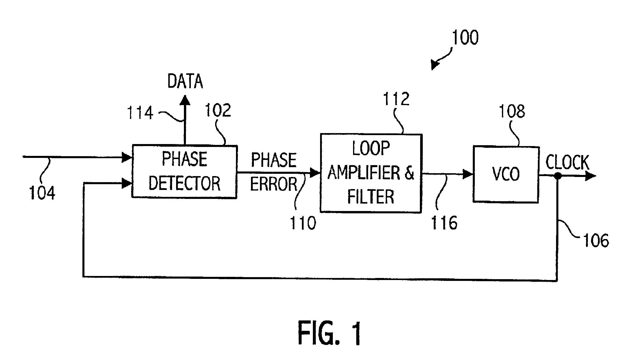
BACKGROUND OF THE INVENTION1. Field of the InventionThe present invention relates to data communication and more particularly to acquisition of a clock signal associated with the data communication.2. Description of the Related ArtCommunication systems frequently transmit data in which the clock is embedded in the data stream rather than sent as a separate signal. When the data stream is received, a clock and data recovery circuit recovers the embedded clock and retimes the received data to the recovered clock. Traditionally, a phase-locked loop (PLL) has been used to perform the clock recovery operation. FIG. 1 shows a block diagram of a traditional PLL configured for a clock and data recovery application. The phase-locked loop 100 includes a phase detector 102, which receives the input data signal conveyed on node 104 and also receives the VCO output clock signal conveyed on node 106 from the voltage controlled oscillator (VCO) 108. The phase detector 102 generates an error signal...

Claims


Application Information

Patent Timeline
IPC IPC(8): H03D3/00H03D3/24H03L7/00H03L7/085H03L7/099H03L7/10H04L1/20H04L7/033H04L27/00
CPCH03L7/085H03L7/099H03L7/10H04L1/205Y10S331/02H04L7/033H04L2027/0016H03L7/113
Inventor PERROTT, MICHAEL H.
Owner SKYWORKS SOLUTIONS INC
Learn More