Apparatus and method for user control of appliances

a technology for appliances and user control, applied in the field of access control, can solve the problems of not being able to be used against him, and the thief cannot be used in the perpetration of other crimes, so as to prevent the use of unsafe appliances, prevent injury, and prevent the effect of household firearm accidents

Inactive Publication Date: 2005-02-15
WOOTTON JOHN R +2
View PDF14 Cites 68 Cited by
  • Summary
  • Abstract
  • Description
  • Claims
  • Application Information

AI Technical Summary

Benefits of technology

use it safely. It is a particular advantage of the invention to prevent unsafe use of the appliance, even by an authorized user.
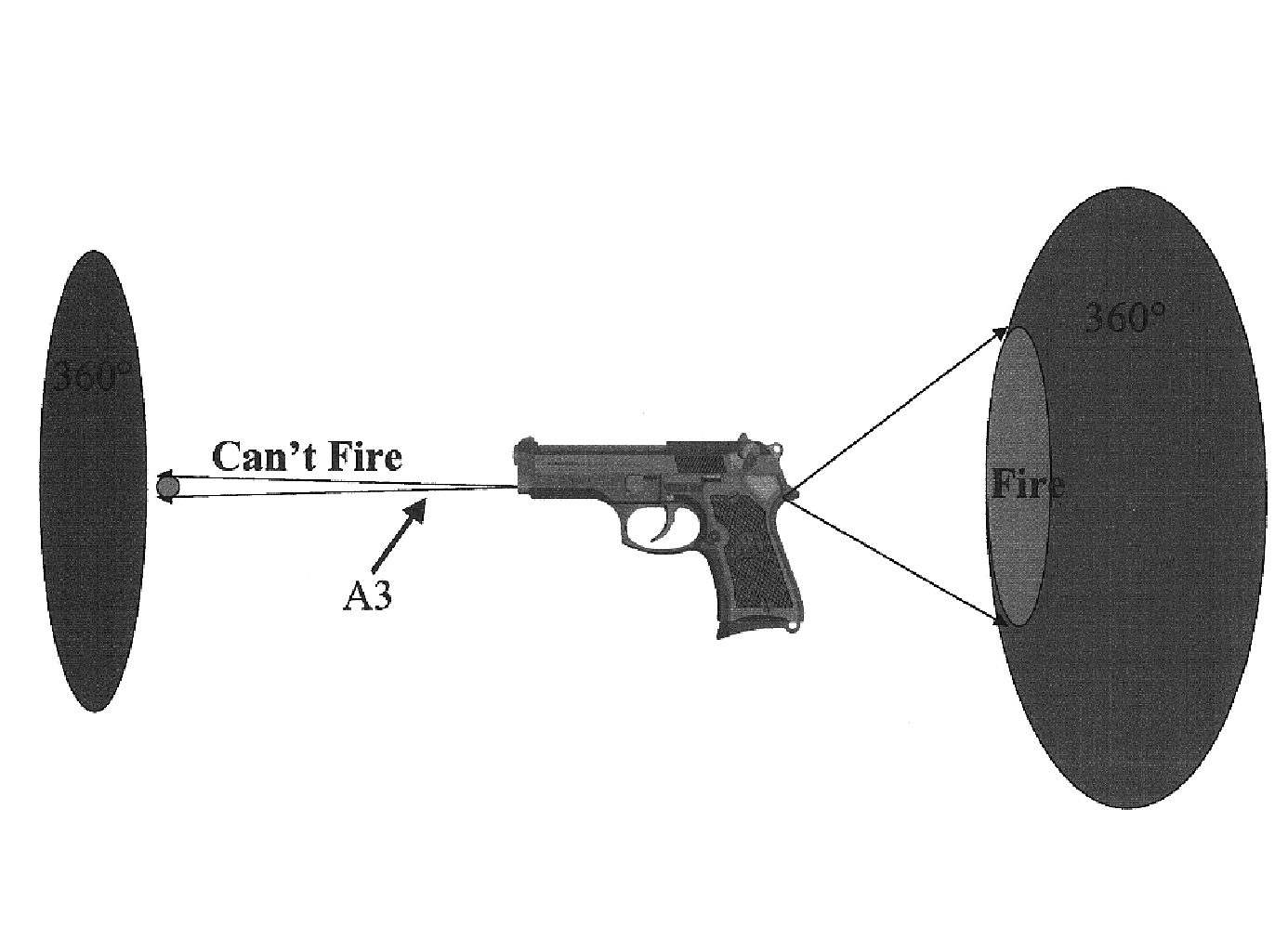
The apparatus and method of the invention are, in one application, used for firearm safety. The apparatus, when used with a firearm enables a policeman or law enforcement agent to enable (authorize) the firearm, so it can be used while the person is on duty. Most importantly, the apparatus and method of the invention only enables the weapon to be fired when the authorized user is in a preferred position with respect to the weapon; i.e., behind it with the muzzle of the weapon pointed away from him. Thus, even if the weapon is taken away from him and he is still in close proximity to it, it cannot be used against him. This feature also is significant in non-law enforcement environments. Use of the apparatus and method with sporting firearms would prevent injury to hunters, for example, who might trip and fall while carrying a loaded rifle or shotgun. The prevention of household firearm accidents is also prevented because even if a child finds a loaded gun, he cannot accidentally discharge it. If the weapon is stolen, it cannot be used by the thief in the perpetration of other crimes.
Another feature of the invention is that more than one individual can b

Problems solved by technology

Thus, even if the weapon is taken away from him and he is still in close proximity to it, it cannot be use

Method used


Image

  • Apparatus and method for user control of appliances
  • Apparatus and method for user control of appliances
  • Apparatus and method for user control of appliances

Examples


Embodiment Construction

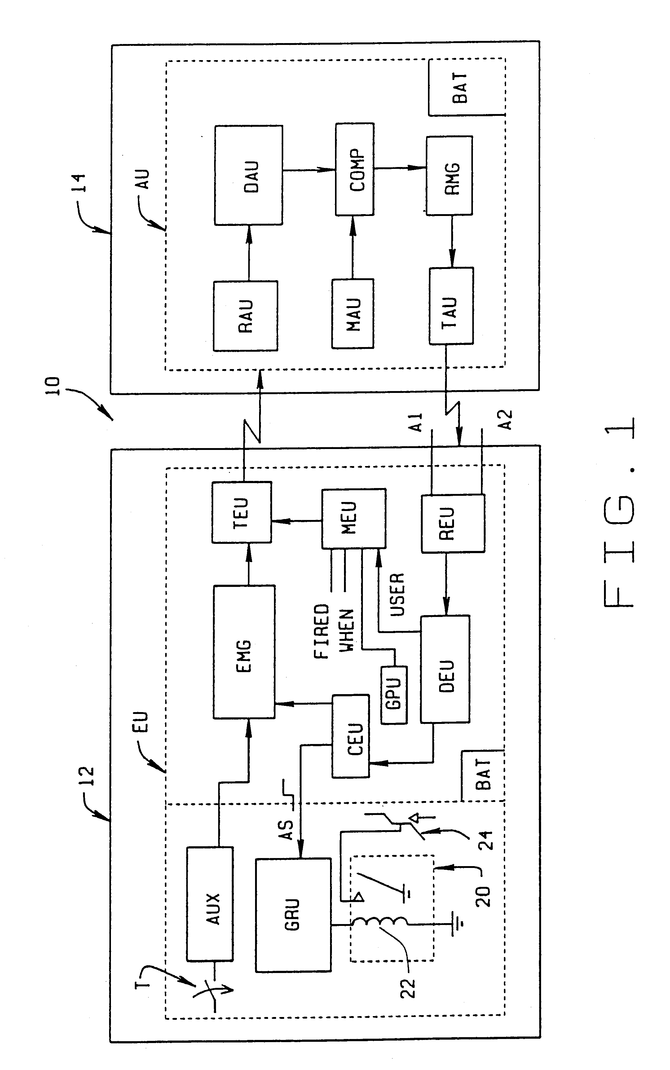
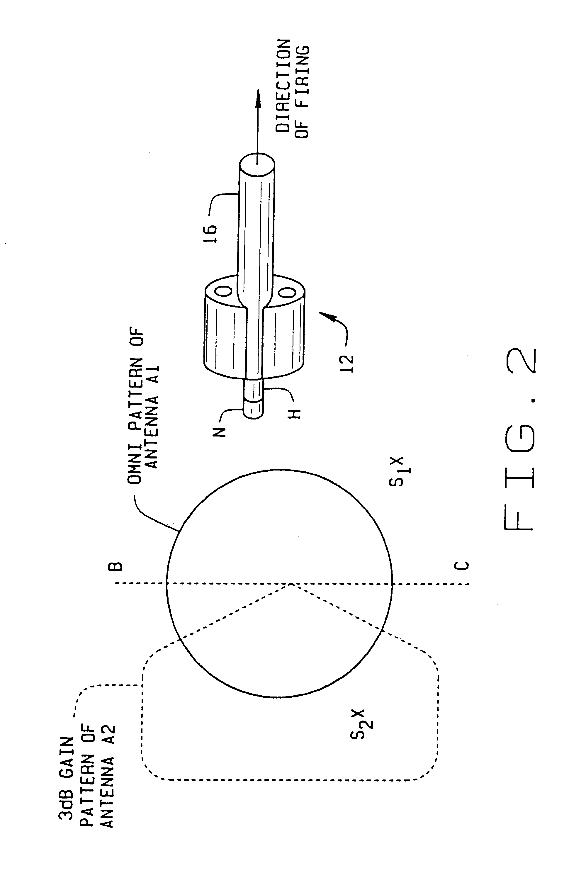
Referring to the drawings, apparatus of the present invention for providing user control of an appliance is indicated generally 10. A representative illustration of the apparatus and method of the invention, and their use is a gun safety mechanism such as described with respect to FIGS. 1 and 2, and FIGS. 5A-5C.

As now described, a key feature of the mechanism is the communication and cooperation between an electronic unit EU contained within a gun 12, and a separate, authorizing unit AU carried by an “authorized user” of the gun. The authorizing unit is, for example, incorporated in a badge 14 worn by a policeman when on duty. Electronic unit EU, which is mounted or otherwise installed within gun 12, first includes an electronic message generator EMG. Generator EMG generates a uniquely coded waveform which, as shown in FIG. 1, is transmitted by a transmitter TEU as an rf signal to authorizing unit AU to interrogate the authorizing unit. As further discussed hereinafter, apparatus 10...


PUM


Abstract

Apparatus (10) and a method for rendering a weapon (12) incapable of use unless authorized by a specified individual. More than one person may be authorized to use the weapon, however only one person may be authorized to use it at any one time. Each authorized person carries a badge (14) or other device which includes an rf transmitter (TAU) capable of transmitting a coded signal to a receiver (REU) installed in the weapon in response to a coded query from a unit (EU) installed in the weapon. If a properly coded transmission is received by the weapon, it becomes capable of being fired by the person who authorized its use. However, the weapon will not fire unless the person using the weapon is also standing behind the weapon. This prevents the weapon from being turned on the person authorized to use it. The apparatus stores details of the weapon's use (e.g., who, when, and where). This information is released upon receipt of an authorized code.

Description

STATEMENT REGARDING FEDERALLY SPONSORED RESEARCH OR DEVELOPMENTNot applicable.BACKGROUND OF THE INVENTIONThis invention relates to access control, and more particularly to user control of appliances. The appliances include a wide range of appliances such as personal computers, firearms including handguns, rifles, and shotguns, as well as other user controlled devices. An apparatus and method of the present invention facilitate usage of an appliance only by an authorized user or users. A particular example of the invention described herein relates to firearm safety by which only someone authorized to use a firearm can fire the weapon, and then only when that authorized person is in a preferred position (i.e., behind) with respect to the weapon. Further, the act of firing the weapon (or usage of the appliance) is recorded so data is subsequently available as to who fired the weapon and when it was fired. With respect to other appliances, the recorded information would indicate who use...

Claims


Application Information

Patent Timeline
IPC IPC(8): F41A17/06F41A17/00
CPCF41A17/063
Inventor WOOTTON, JOHN R.MATTHEWS, F. MAURYMULLER, J. JOSEPH
Owner WOOTTON JOHN R
Why Eureka
Try Eureka