
Method of measuring a physical function using a composite function which includes the physical function and an arbitrary reference function

a composite function and physical function technology, applied in the field of measuring the attributes of a physical system, can solve the problems of wide discrepancies, lack of reliable method for measuring nonlinearity profiles, and lack of reliable procedure for measuring nonlinear profiles

Inactive Publication Date: 2005-02-15
THE BOARD OF TRUSTEES OF THE LELAND STANFORD JUNIOR UNIV
View PDF10 Cites 14 Cited by
  • Summary
  • Abstract
  • Description
  • Claims
  • Application Information

AI Technical Summary

Benefits of technology

"The present invention provides methods for measuring various optical properties of a sample, such as second-order optical nonlinearity, temporal waveform, and physical function. These methods involve forming a composite sample with the sample and a reference material, measuring the Fourier transform of the nonlinearity profile, and calculating the inverse Fourier transform to obtain information about the nonlinearity profile. The methods can be used to measure the nonlinearity profile of a sample optical pulse and to determine the temporal waveform of a sample. The invention also provides reference materials for use in these methods. The technical effects of the invention include improved accuracy and precision in measuring optical properties of samples and improved accuracy in determining the temporal waveform of samples."

Problems solved by technology

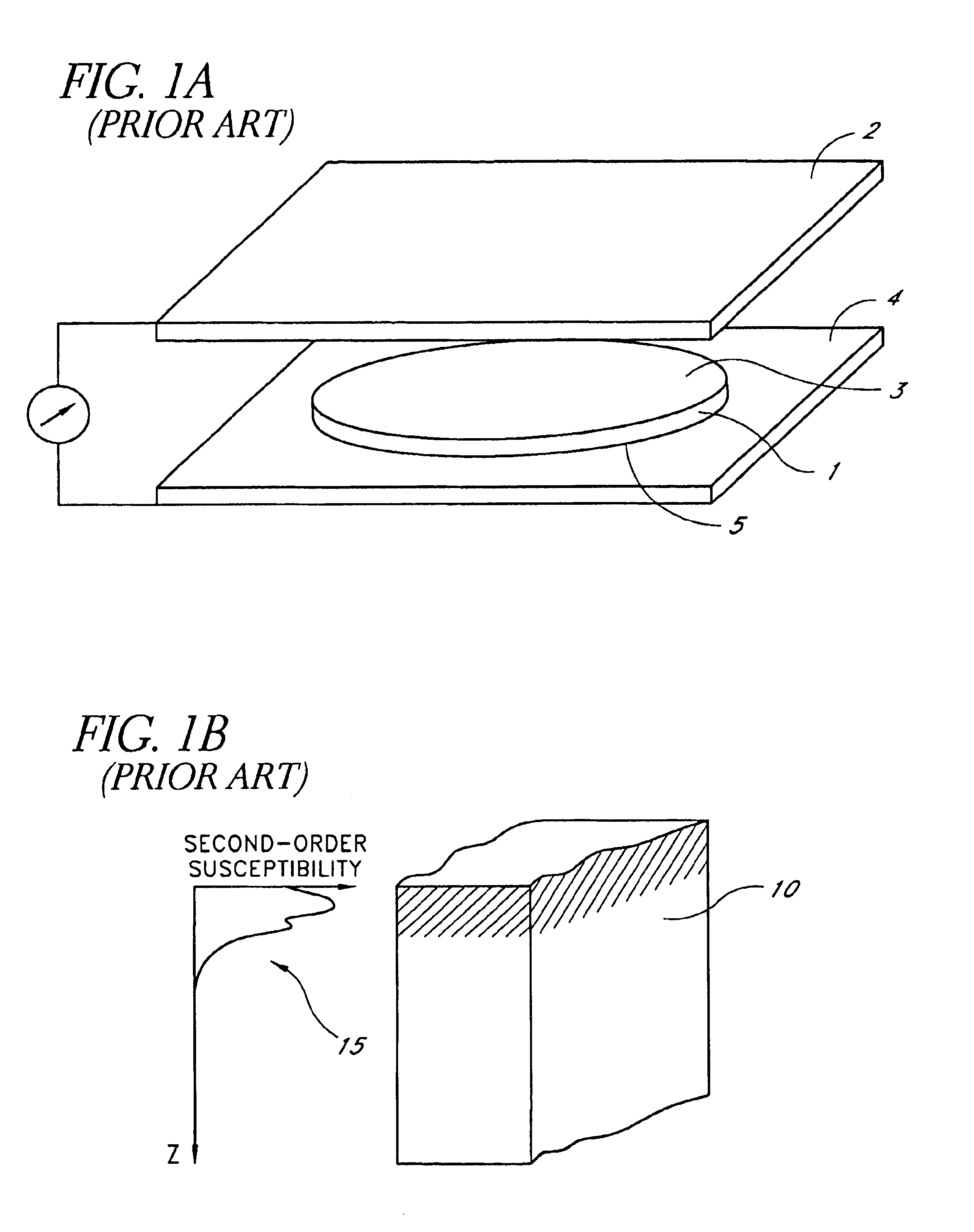
The field of poled silica has suffered from the lack of a common method to reliably measure the second-order optical nonlinearity profile of poled samples.
This absence of a reliable procedure for measuring nonlinearity profiles may be the reason, at least in part, for wide discrepancies in the measured magnitudes and the positions of the nonlinearity profiles of various poled systems as reported in the literature.
Consequently, for an arbitrary and unknown nonlinearity profile, the MF measurement alone is not sufficient to determine a unique solution for d33(z).
Even if the phase information were available, it would provide the shape of d33(z) but it would still not provide the location of this shape beneath the surface of the sample (i.e., where the nonlinearity profile starts beneath the surface).
However, the previous methods do not produce a unique solution for d33(z).

Method used


Image

  • Method of measuring a physical function using a composite function which includes the physical function and an arbitrary reference function
  • Method of measuring a physical function using a composite function which includes the physical function and an arbitrary reference function
  • Method of measuring a physical function using a composite function which includes the physical function and an arbitrary reference function

Examples


Embodiment Construction

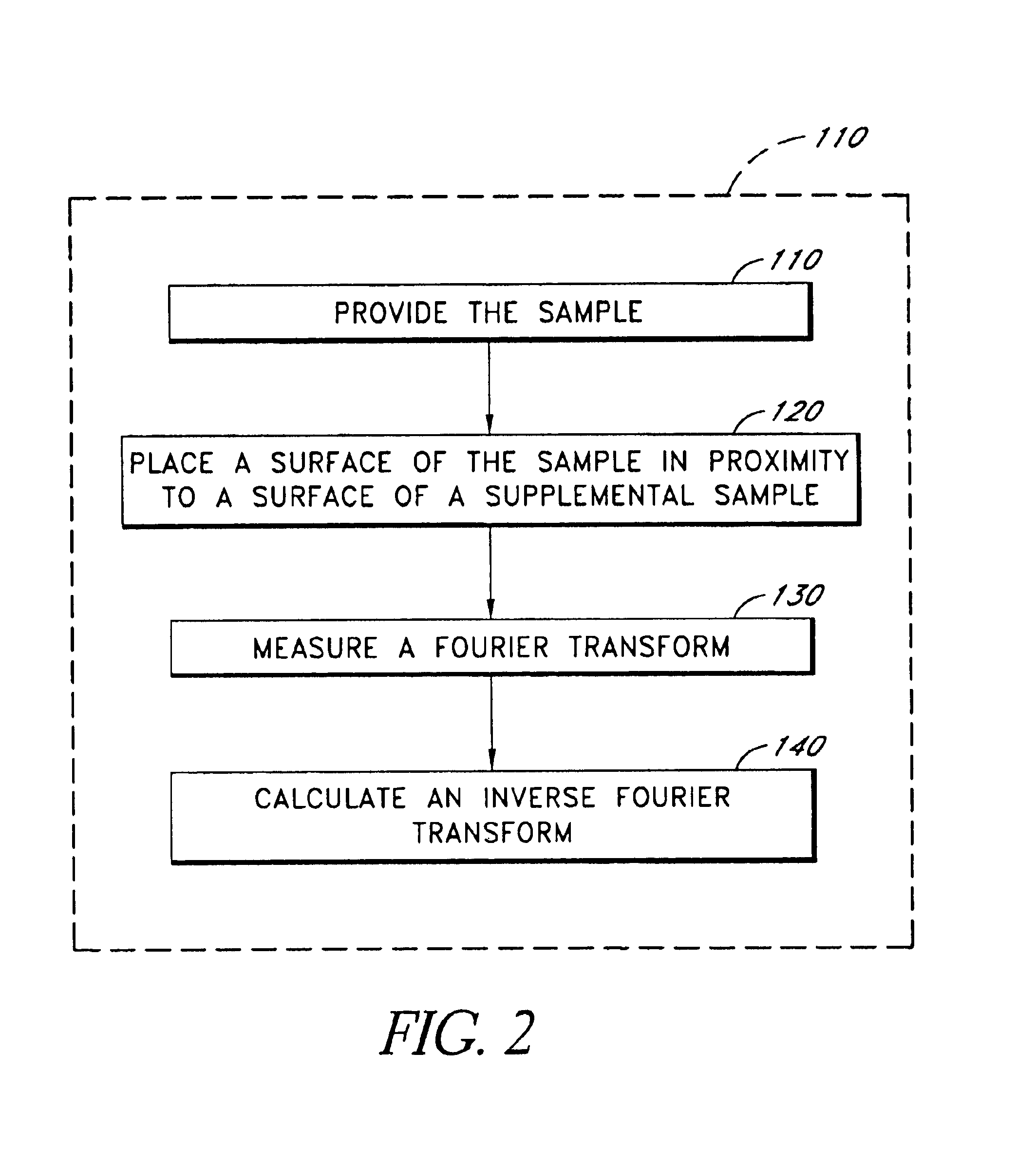
FIG. 2 is a flow diagram of a method 100 of measuring a second-order optical nonlinearity profile of a sample 10 in accordance with embodiments of the present invention. While the flow diagrams herein illustrate particular embodiments with steps in a particular order, other embodiments with different orders of steps are also compatible with the present invention.

In the method 100, the sample 10 is provided in an operational block 110. The sample 10 has the second-order optical nonlinearity profile 15 to be measured. In an operational block 120, a surface of the sample 10 is placed proximate to a surface of a supplemental sample 20, as schematically illustrated in FIGS. 3A-3C and 4A-4D. As schematically illustrated in FIG. 3A, the sample 10 and supplemental sample 20 form a composite sample 30 having a symmetric second-order optical nonlinearity profile 35. In an operational block 130, a Fourier transform of the symmetric second-order optical nonlinearity profile 35 is measured. In a...


PUM

PropertyMeasurementUnit
incident angleaaaaaaaaaa
time-reversed temporalaaaaaaaaaa
timeaaaaaaaaaa

Abstract

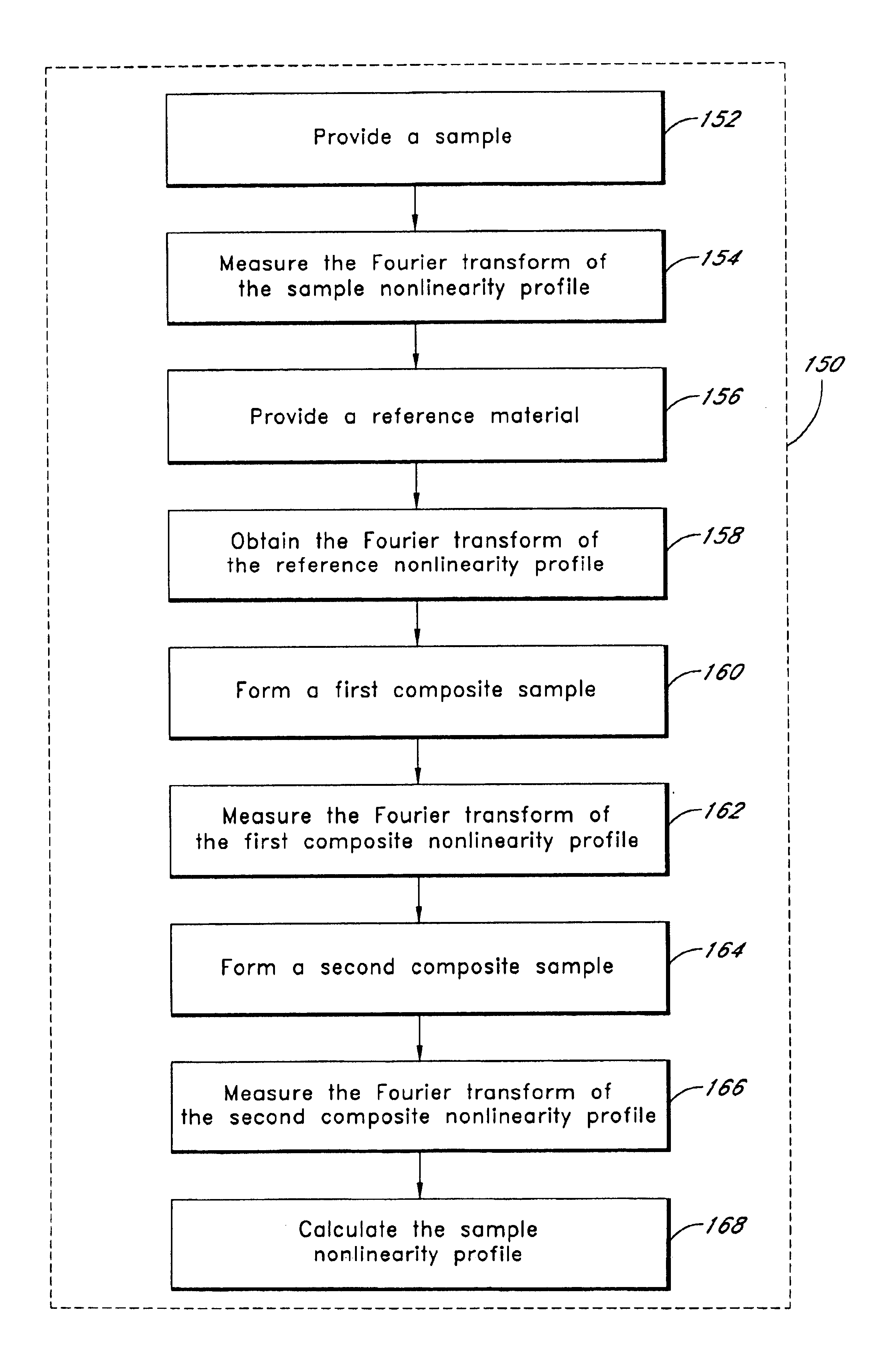
A method measures a nolinearity profile of a sample with at least one sample surface and having a sample nonlinearity profile along a sample line through a predetermined point on the sample surface. The sample line is oriented perpendicularly to the sample surface. The method includes measuring a Fourier transform of the sample nonlinearity profile and obtaining a reference nonlinearity profile from a reference material. The method includes forming a first composite sample having a first composite nonlinearity profile and forming a second composite sample having a second composite nonlinearity profile inequivalent to the first composite nonlinearity profile. The method further includes measuring a Fourier transform of the first composite nonlinearity profile and measuring a Fourier transform of the second composite nonlinearity profile. The method further includes calculating the sample nonlinearity profile using the Fourier transforms of the sample nonlinearity profile, the reference nonlinearity profile, the first composite nonlinearity profile, and the second composite nonlinearity profile.

Description

BACKGROUND OF THE INVENTION1. Field of the InventionThe present invention relates generally to the field of measuring attributes of a physical system, and more particularly to methods of measuring a non-symmetric physical function.2. Description of the Related ArtVarious optical devices are based on induced second-order susceptibilities in silica-based glass waveguides (e.g., electro-optic modulators, switches, parametric amplifiers). For example, G. Bonfrate et al. describe optical parametric oscillators useful for the study of quantum interference and quantum cryptography, and for metrology applications in Parametric Fluorescence in Periodically Poled Silica Fibers, Applied Physics Letters, Vol. 75, No. 16, 1999, pages 2356-2358, which is incorporated in its entirety by reference herein. Second-order susceptibility can be induced in a several-microns-thick region of fused silica (a material that is not normally centro-symmetric, and therefore normally does not exhibit a second-ord...

Claims


Application Information

Patent Timeline
Patent Type & Authority Patents(United States)
IPC IPC(8): G01N21/63G01J11/00
CPCG01J11/00G01N21/21G01N21/636G01N21/4788G01N2021/4735G01N2021/4723
Inventor OZCAN, AYDOGANDIGONNET, MICHEL J.F.KINO, GORDON S.
Owner THE BOARD OF TRUSTEES OF THE LELAND STANFORD JUNIOR UNIV
Learn More