Multiple imaging system

a multi-spectral imaging and filter wheel technology, applied in the field of multi-spectral imaging systems, can solve the problems of difficult comparison of images made on the two imaging sensors, three imaging sensors, and insufficient filter wheel-dependent multi-spectral systems,

Inactive Publication Date: 2005-02-15
FOSTER-MILLER
View PDF48 Cites 52 Cited by
  • Summary
  • Abstract
  • Description
  • Claims
  • Application Information

AI Technical Summary

Problems solved by technology

In cases where it is important to produce differently-filtered images simultaneously, filter-wheel-dependent multi-spectral systems are inadequate.
One major drawback with this system is that three imaging sensors, which can often be quite expensive, are required.
For example, something as simple as a slight difference in temperature stability between two imaging sensors can make very fine comparisons of images made on the two imaging sensors practically impossible.
Because of the convoluted orientation of the multiple off-axis mirrors in these designs, complex positioning systems are required., These patents also describe apparatuses that do not to minimize vignetting.
Positioning of the prism at a point in the optical train where light is converging introduces a number of aberrations and degrades image quality.
Furthermore, positioning of the filter array at a point in the optical train where light is converging necessarily causes light to be incident on the filters at a wide range of angles (corresponding to the angles at which the light is converging).
Furthermore, this apparatus does not minimize vignetting.
This presents the same shortfalls presented in the case where a filter array is placed in a converging beam.
Furthermore a system of two, concentrically located prisms is required, which is more complicated to align than a single prism would be.

Method used


Image

  • Multiple imaging system
  • Multiple imaging system
  • Multiple imaging system

Examples


Embodiment Construction

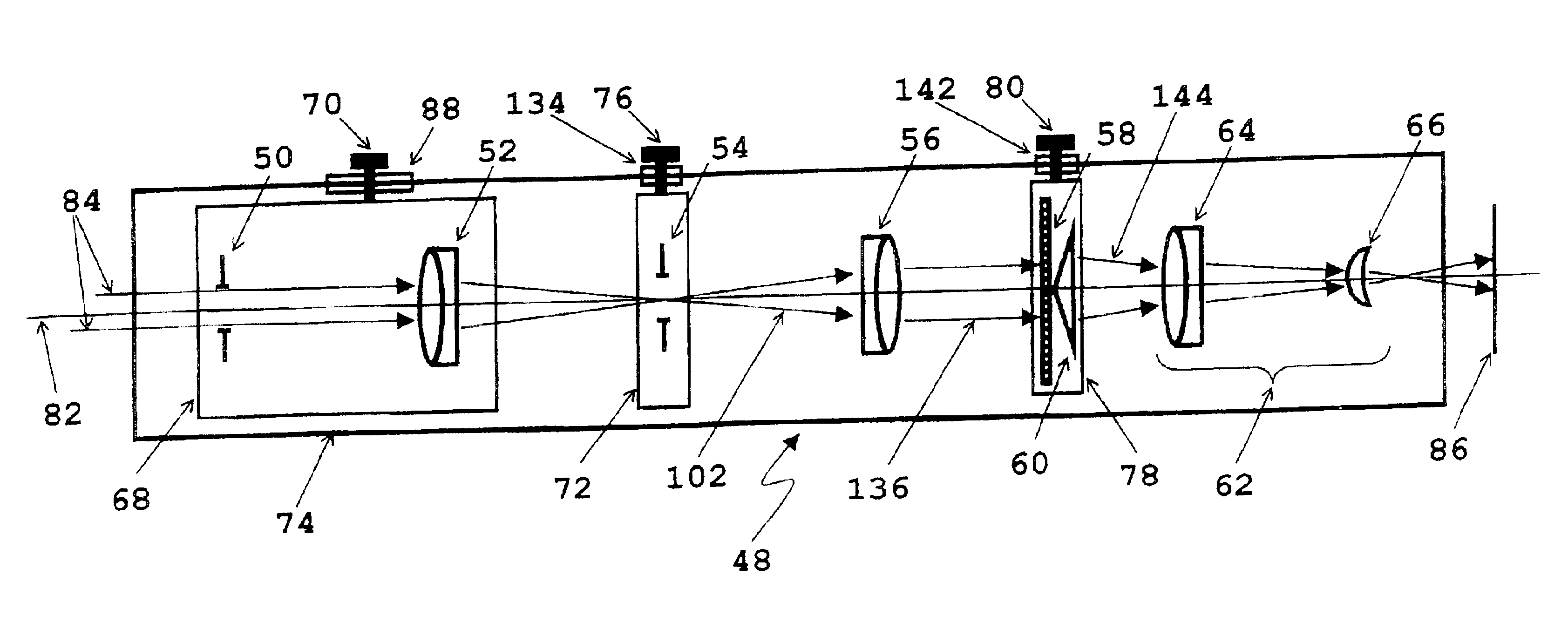
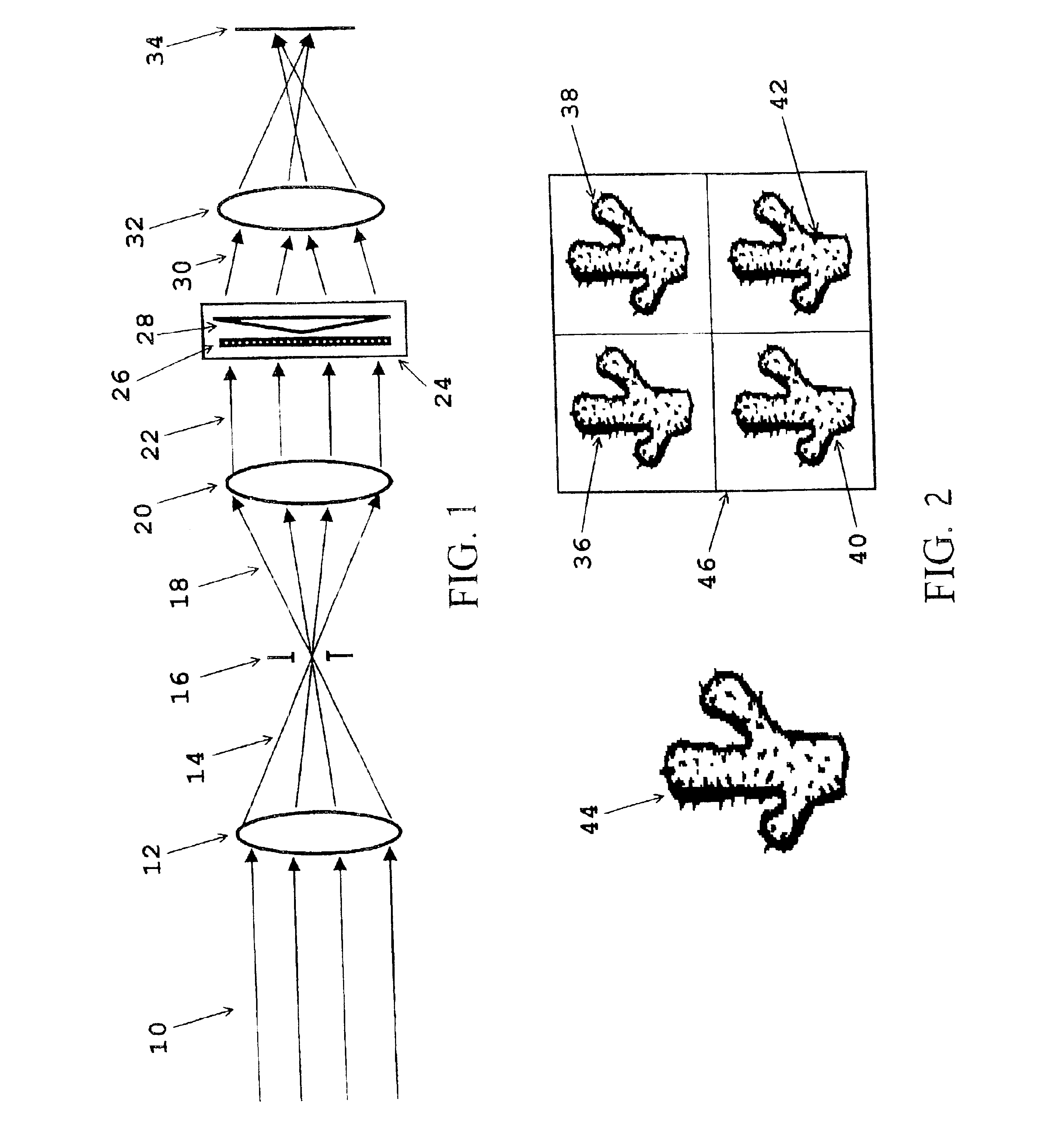
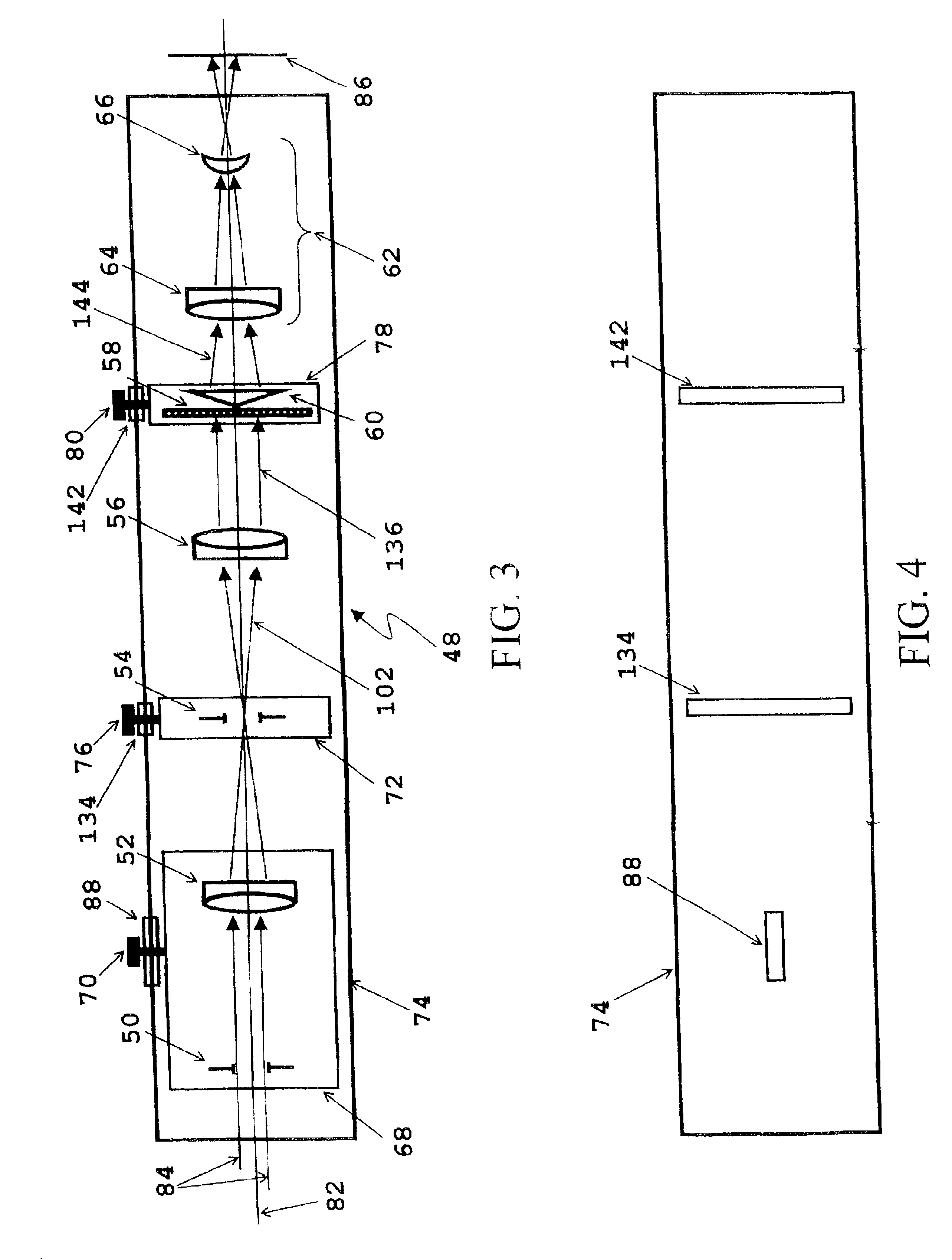
The basic concept of the present invention involves telecentrically forming a first image of a distant object, masking the edges of the first image, collimating light from the first image, filtering and then beam-separating the collimated light, and then forming a plurality of separate images on a single imaging plane. FIG. 1 shows a schematic diagram of the present invention.

Referring to FIG. 1, optical radiation 10 from a distant object (not shown) is incident on a first telecentric imaging lens 12 (also referred to as the first telecentric optical sub-system). The first telecentric imaging lens 12 focuses the optical radiation 14 and forms a first image at a plane substantially coincident with a rectangular aperture 16. After focusing to an image at a plane substantially coincident with a rectangular aperture 16, optical radiation next diverges 18 and is incident on a second telecentric imaging lens 20 (also referred to as the second telecentric optical sub-system). The second te...


PUM


Abstract

A series of optical elements is used to produce multiple simultaneous adjoining images on a single image plane. A first, intermediate, image is produced using the first telecentric imaging lens. This intermediate image is produced at a plane coincident with an adjustable-size rectangular field stop. The rectangular field stop is mounted in a sub-housing that allows its free rotation. A second telecentric lens collimates the light from the intermediate image. This collimated light is next passed through an optical splitting means, which uses the principal of refraction to separate the light into multiple components. The optical splitting means is mounted in a sub-housing that allows its free rotation. From here, the light next passes through a third and final lens, which produces a second, final, image on a single, planar detection device. The final image consists of a plurality of identical copies of the intermediate image.

Description

BACKGROUND OF THE INVENTIONThis invention relates generally to imaging systems and more particularly to an imaging system that produces multiple images of a single object scene onto a single detector array. These multiple images are spatially displaced from one another on a single detector array in the image plane.In some specialized applications, such as long-range multi-spectral imaging, there is a great desire to produce several images of a given object scene simultaneously on a single detector array (such as a CCD). For applications such as multi-spectral imaging, each of these separate images is passed through a different colored filter. Presently, multi-spectral imaging is typically performed either with rotating filter wheels (which are unable to record more than a single image simultaneously) or with a plurality of imaging and detection systems (which inherently are unable to image onto a single detector array).Multi-spectral systems that rely on rotating filter wheels produ...

Claims


Application Information

Patent Timeline
Patent Type & Authority Patents(United States)
IPC IPC(8): G02B27/28
CPCG02B27/1013G02B27/126G02B27/1066
Inventor TOCCI, MICHAEL D.
Owner FOSTER-MILLER
Why Eureka
Try Eureka