System and method for statistical control of power dissipation with host enforcement

a power dissipation and statistical control technology, applied in the field of data communication, can solve the problems of limited transceiver activity, throttled transmit and receiver rate, limited data flow through the active transceiver during the next (second) time period, etc., and achieve the effect of data flow ra

Inactive Publication Date: 2005-02-15
RPX CORP
View PDF9 Cites 84 Cited by
  • Summary
  • Abstract
  • Description
  • Claims
  • Application Information

AI Technical Summary

Benefits of technology

The present invention, a power budgeter, controls the rate of data flow in a plurality of transceivers. The power budgeter is implemented by monitoring aggregate transceiver activity (data flow) during a predefined period (such as one second), and limiting transceiver data transmit and receive rates during times when the aggregate transceiver activity would otherwise exceed a predefined threshold. If total data flow in the monitored time period exceeds the threshold, data flow through the active transceiver during the next (second) time period is limited. Data flow rates are limited in a transceiver by shutting off transceivers (receiver and / or transmitter) for a specified portion of the second time period. In other types of transceivers, the transmitter and / or receiver may be forced into a low-power idle state or similar operating condition for a specified portion of the second predefined time period.

Problems solved by technology

If total data flow in the monitored time period exceeds the threshold, data flow through the active transceiver during the next (second) time period is limited.
However, if a sufficient number of transceivers are active, such that the total heat dissipation of the active transceivers would exceed the specified limit of the multiple transceiver unit during the monitored time period, the power budgeter operates such that transceiver activity is limited (actual data transmit and receiver rates are throttled back) during the next predefined time period.

Method used


Image

  • System and method for statistical control of power dissipation with host enforcement
  • System and method for statistical control of power dissipation with host enforcement
  • System and method for statistical control of power dissipation with host enforcement

Examples


Embodiment Construction

A. Overview of the Power Budgeting System and Method

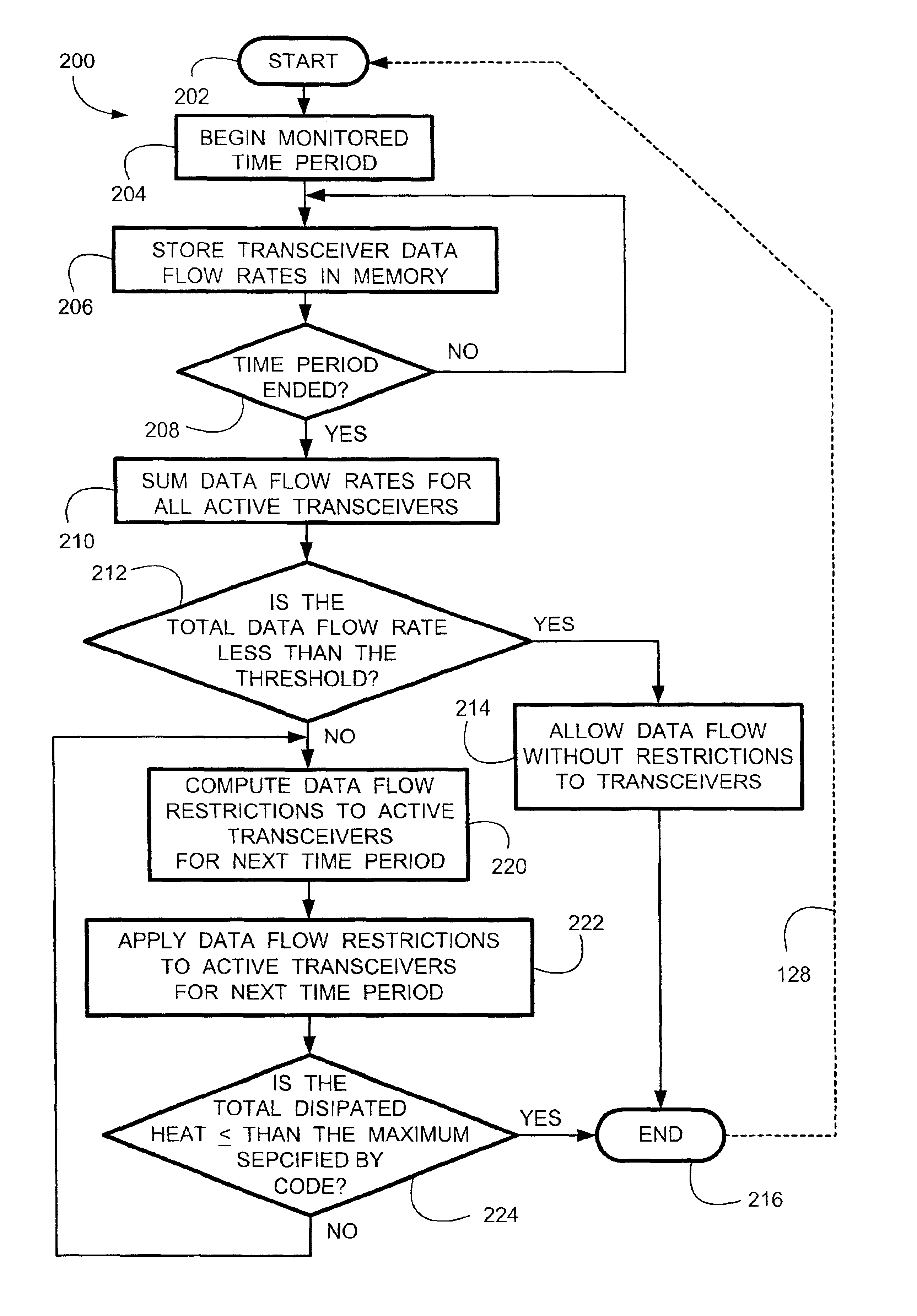
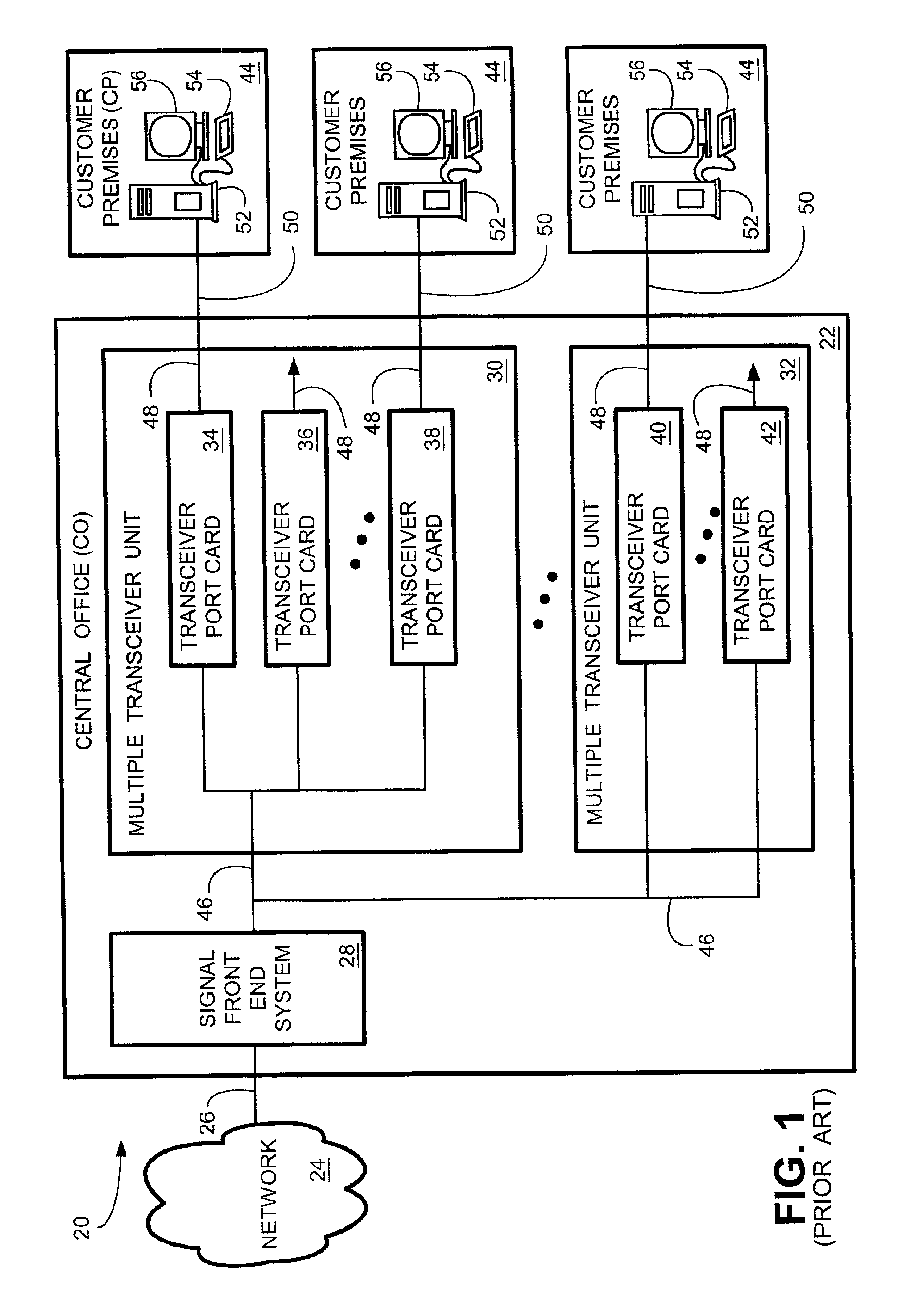
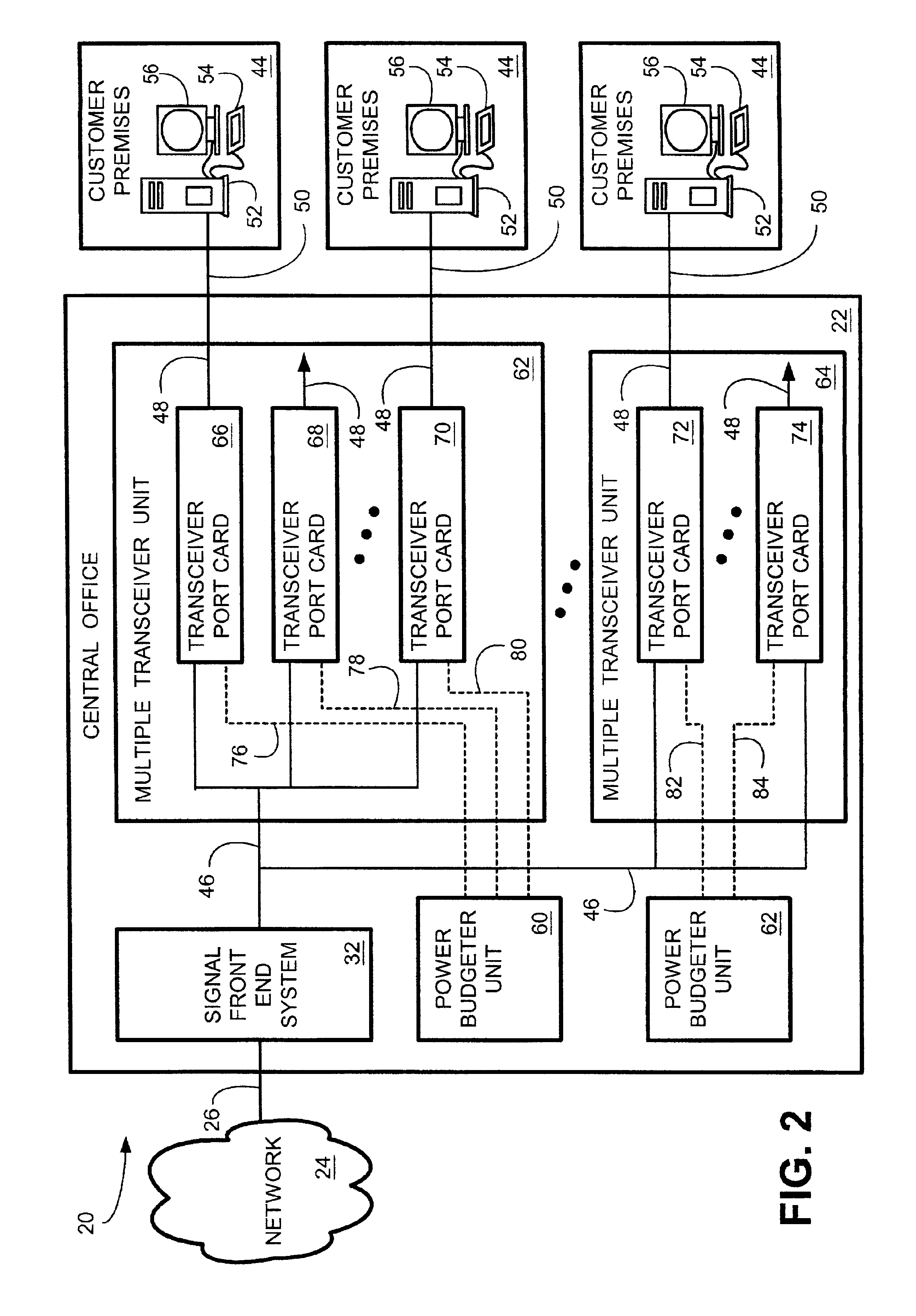
The present invention, a power budgeter, controls the rate of data flow in one or more transceivers among a plurality of transceivers. A transceiver is typically mounted on a transceiver port card that is installed in a multiple transceiver unit, usually a large cabinet enclosure for housing the transceiver port cards and other various components. It is desirable to limit power consumption in each individual transceiver during times when a plurality of transceivers are actively transmitting or receiving data. Limiting the power consumption in a transceiver reduces the heat dissipated by the transceiver. Power in an individual transceiver is reduced by limiting the rate that the transceiver is transmitting or receiving data. Thus, the present invention, a power budgeter, is implemented by monitoring aggregate transceiver activity during a predefined period (such as one second), and limiting transceiver data transmit and receive rate...


PUM


Abstract

The power budgeter controls the rate of data flow in one or more transceivers among a plurality of transceivers. The power budgeter monitors aggregate transceiver activity (data flow) during a predefined period, and limits transceiver data transmit and receive rates during times when the aggregate transceiver activity would otherwise exceed a predefined threshold. If total data flow during the monitored time period exceeds the threshold, data flow through the active transceiver during the next (second) time period is limited. Data flow rates are limited in a transceiver by shutting off transceivers (receiver and/or transmitter) for a specified portion of the second time period. In other types of transceivers, the transmitter and/or receiver may be forced into a low-power idle state or similar operating condition for a specified portion of the second predefined time period.

Description

TECHNICAL FIELDThe present invention relates generally to data communications, and more particularly, to a system and method for managing power consumption in a transceiver.BACKGROUND OF THE INVENTIONWith the increasing bandwidth demands from the advent of the Internet, service providers have looked for ways to increase data transmission performance over the copper wire local loop transmission lines that connect telephone central offices (COs) to customer premises (CPs). In conventional telephony networks, customer premises equipment (CPE) are coupled to CO switches over the above mentioned transmission lines, which are commonly known as “local loops,”“subscriber lines,”“subscriber loops,”“loops,” or the “last mile” of the telephone network. In the art, the term “line” and “loop” are used interchangeably, both terms referring to the copper wire pair used in a typical telephone transmission line conductor. Historically, the public switched telephone network (PSTN) evolved with subscr...

Claims


Application Information

Patent Timeline
Patent Type & Authority Patents(United States)
IPC IPC(8): H04L12/28H04L12/12
CPCH04L12/12H04L12/2856H04L12/2898Y02B60/34Y02B60/32Y02B60/33Y02D30/50
Inventor SCOTT, BOB
Owner RPX CORP
Why Eureka
Try Eureka