
Method and apparatus for isolating faults in a switching matrix

a switching matrix and fault technology, applied in the field of routing devices, can solve problems such as failure detection

Inactive Publication Date: 2005-02-15
CISCO TECH INC
View PDF15 Cites 273 Cited by
  • Summary
  • Abstract
  • Description
  • Claims
  • Application Information

AI Technical Summary

Problems solved by technology

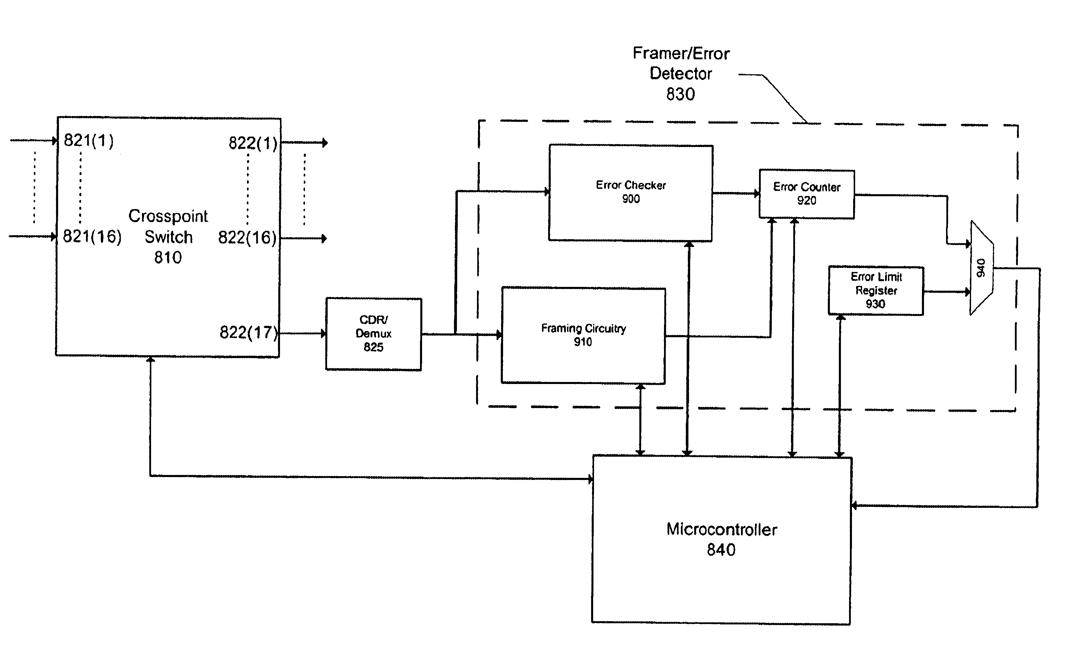
If one of the switching matrixes experiences a failure, the failure is detected by a corresponding error detector.

Method used


Image

  • Method and apparatus for isolating faults in a switching matrix
  • Method and apparatus for isolating faults in a switching matrix
  • Method and apparatus for isolating faults in a switching matrix

Examples


Embodiment Construction

The following is intended to provide a detailed description of an example of the invention and should not be taken to be limiting of the invention itself. Rather, any number of variations may fall within the scope of the invention which is defined in the claims following the description.

In addition, the following detailed description has been divided into sections, subsections, and so on, in order to highlight the various subsystems of the invention described herein; however, those skilled in the art will appreciate that such sections are merely for illustrative focus, and that the invention herein disclosed typically draws its support from multiple sections. Consequently, it is to be understood that the division of the detailed description into separate sections is merely done as an aid to understanding and is in no way intended to be limiting.

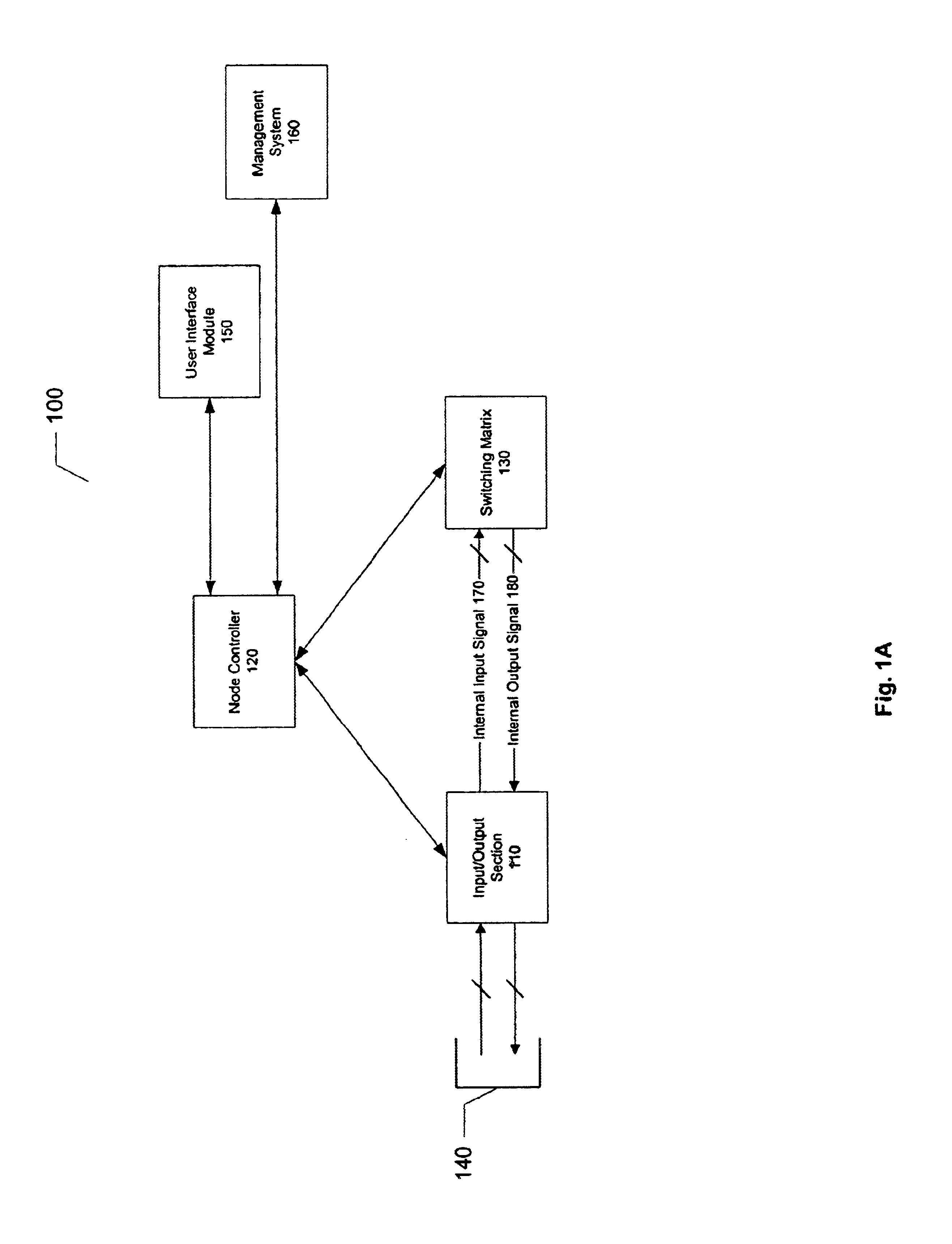
FIG. 1A illustrates a router 100. Router 100 includes an input / output section 110, a node controller 120, and a switching matrix 130. Node c...


PUM


Abstract

A signal router is described. The signal router includes a switching matrix, an error detector and a controller. The switching matrix includes a first number of inputs and a second number of outputs, and is configured to receive an information stream. The error detector is coupled to one of the second number of outputs, and is configured to generate error information by virtue of being configured to detect errors in the information stream. Likewise, the controller is coupled to the switching matrix and error detector. The controller is configured to select one of the first number of inputs, receive error information from the error detector, and configure the switching matrix to couple the selected input to one of the outputs.

Description

BACKGROUND OF THE INVENTION1. Field of the InventionThis invention relates to the field of information networks, and more particularly relates to a router capable of routing information over a network.2. Description of the Related ArtToday's networks carry vast amounts of information. High bandwidth applications supported by these networks include streaming video, streaming audio, and large aggregations of voice traffic. In the future, these demands are certain to increase. To meet such demands, an increasingly popular alternative is the use of lightwave communications carried over fiber optic cables. The use of lightwave communications provides several benefits, including high bandwidth, ease of installation, and capacity for future growth.The synchronous optical network (SONET) protocol is among those protocols designed to employ an optical infrastructure and is widely employed in voice and data communications networks. SONET is a physical transmission vehicle capable of transmiss...

Claims


Application Information

Patent Timeline
Patent Type & Authority Patents(United States)
IPC IPC(8): G06F11/00H04Q11/00
CPCH04L41/0681H04L43/0847H04L41/0659H04Q2011/0058H04L41/0896
Inventor RUSSELL, RONALD ALANANTHONY, MICHAEL KEVIN
Owner CISCO TECH INC
Learn More