Multicast cell scheduling protocol

a multicast cell and scheduling protocol technology, applied in the field of data handling systems, can solve the problems of difficult multicast data cell transmission, and difficult to solve the problem of simple allocation problem

Inactive Publication Date: 2005-02-15
PMC-SIERRA
View PDF7 Cites 90 Cited by
  • Summary
  • Abstract
  • Description
  • Claims
  • Application Information

AI Technical Summary

Benefits of technology

In accordance with the present invention, a method of facilitating the scheduling of a first multicast request signal of a series of multicast request signals is disclosed, wherein the first request signal is generated to enable the transmission of a multicast data cell by a source port processor to at least one destination port processor.

Problems solved by technology

One problem which exists in the context of packet switching via a crossbar switch is the allocation of available paths through the crossbar.
Given that very disparate patterns can exist in data communication demands, particularly when accommodating data originating from disparate systems, the allocation problem is not a simple one.
Of particular concern for many router system designers are the difficulties encountered in the transmission of multicast data cells.
Several factors make arbitrating paths for and delivery scheduling of multicast cells more complicated than for unicast cells and, if implemented poorly, prone to unacceptable system performance.
First, multicast cells from one ingress linecard and of the same priority with a request label of particular identifying characteristic (i.e., the cells are said to be “in the same flow”) typically share a queue with cells having differing labels, and can thus suffer from head-of-line blocking.
Second, cells with large fanouts may be substantially delayed before their destination outputs become free.
While it is desirable to use the crossbar to copy cells, requiring that all such copies be delivered to their egress switch ports in the same time slot leads to unnecessary additional head-of-line blocking.
This effort is made difficult in large switches by the necessity of distributing the scheduling of the fanout over multiple scheduler chips.
On the other hand, it is desired that scheduling be pipelined (i.e., continually performed in descending order of priority) to maximize the scheduling rate, which in turn makes communication between the chips difficult, particularly when the communication is in the opposite direction to pipeline propagation.

Method used


Image

  • Multicast cell scheduling protocol
  • Multicast cell scheduling protocol
  • Multicast cell scheduling protocol

Examples


Embodiment Construction

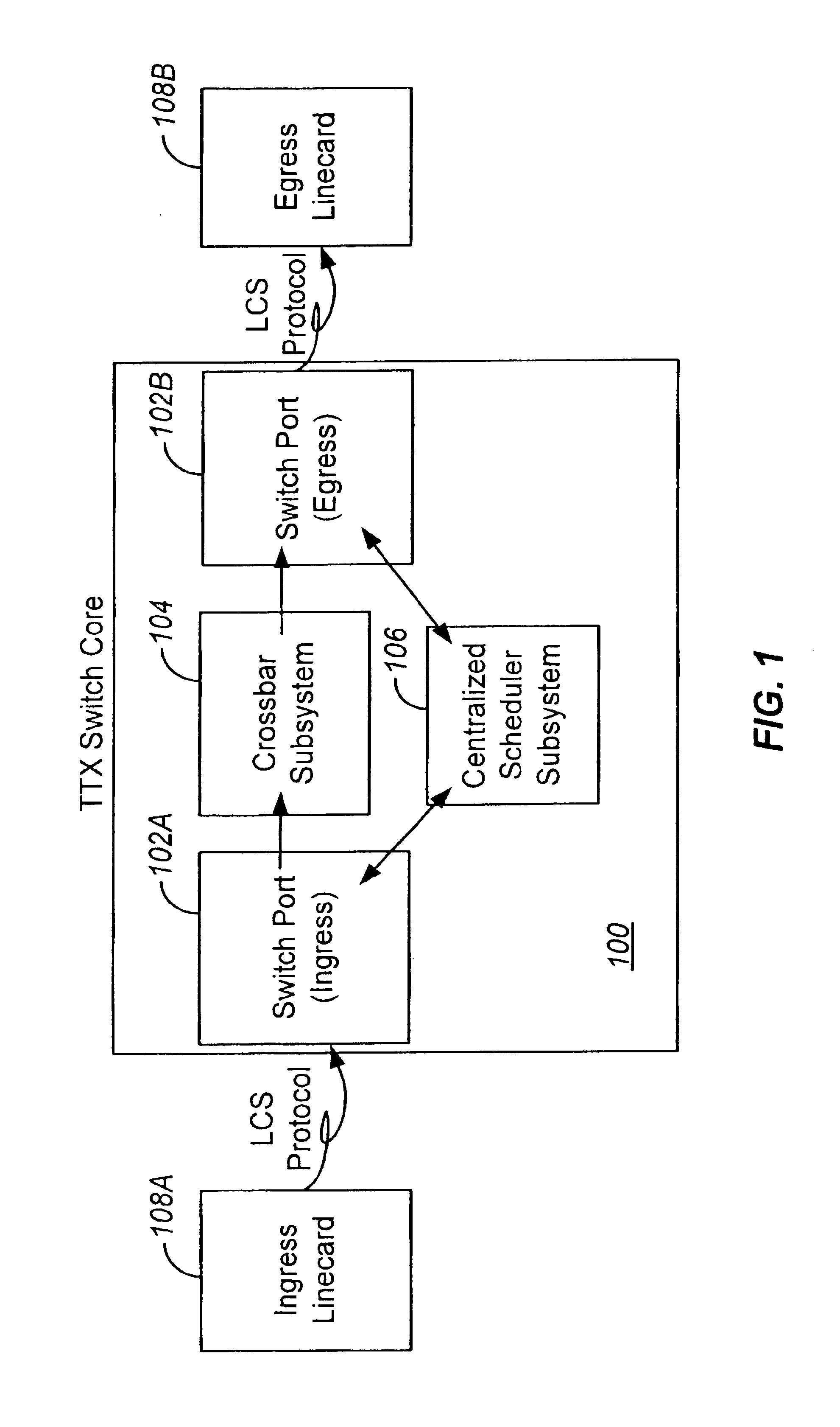
FIG. 1 is a block diagram depicting logical interconnects of a base crossbar-based switch core 100 in accordance with the present invention. The switch core 100, for the purpose of describing the preferred embodiment, includes three types of devices: ports 102A, 102B, crossbar subsystem 104 and centralized scheduler subsystem 106.

Ingress port 102A and egress port 102B are respectively coupled to an ingress linecard 108A and egress linecard 108B, each of linecards 108A, 108B being outside the switch core 100. In a preferred embodiment, the ports 102 include shallow queues and implement a linecard-to-switch (LCS) protocol. Note that, with reference to FIG. 1, ports 102A, 102B are depicted as and may comprise separate instruments; in the preferred embodiment of the present invention, however, ports 102A, 102B comprise an integrated instrument.

The ports 102 may have shallow (e.g., 64 cell) queues in both ingress and egress directions. These queues may compensate for the latency between ...


PUM


Abstract

A method of facilitating the scheduling of a first multicast request signal of a series of multicast request signals is disclosed, wherein the first request signal is generated to enable the transmission of a multicast data cell by a source port processor to at least one destination port processor. In a preferred embodiment of the invention, the first request signal is received by a roster storage chip associated with a scheduler subsystem. The first request signal has associated therewith a multicast label of a first value and is adapted to schedule transmission of the first multicast cell to the at least one destination port processor at a first time. A roster of the at least one destination port processor to which the first multicast cell is destined is then generated. A dependence distance associated with the first request signal is determined. The dependence distance comprises the numerical value of the difference between a current multicast cell number (CMCN) and a previous multicast cell number (PMCN). The roster and the dependence distance are transmitted to one of the at least one scheduler chips, such transmission causing the roster and the dependence distance to occupy a second tail entry slot of a second circular buffer associated with the one of the at least one scheduler chips. The second tail entry slot has associated therewith a first multicast table index (MTI) comprising a numerical value. The scheduler chip further has associated therewith a head entry slot having associated therewith a second MTI comprising a numerical value. A first numerical parameter comprising the numerical sum of the dependence distance and the first MTI is determined. If the first numerical parameter is higher in value than the second MTI, the first request signal is arbitrated.

Description

BACKGROUND OF THE INVENTION1. Field of the InventionThe present invention relates generally to data handling systems and, more particularly, to a system for ensuring the efficient scheduling of data cell request signals that enable accurate and timely routing of data cell packets.2. Description of the Background ArtThere is increasing interest in providing communications between disparate computer systems and even between networks of differing characteristics. Further, with the availability of very high bandwidth trunk lines, e.g., using fiber optic cables, there is increasing interest in combining traffic from a great variety of sources for transmission through a single trunk line. For wide area networks, packet switching technology is widely used where information to be transmitted is broken into packets of data which are preceded by headers containing information useful in routing. The header may also identify the source and the destination. Whether truly packet switched or not, ...

Claims


Application Information

Patent Timeline
Patent Type & Authority Patents(United States)
IPC IPC(8): H04L12/56H04L12/18
CPCH04L12/18H04L49/508H04L49/201H04L49/101H04L49/254
Inventor CALAMVOKIS, COSTASMCKEOWN, NICHOLASRIES, PAUL S.
Owner PMC-SIERRA
Why Eureka
Try Eureka