EMG electrode apparatus and positioning system

a positioning system and electrode technology, applied in the field of electrode apparatus and positioning system, to achieve the effect of increasing the level of signal and increasing the sensitivity of electrodes

Inactive Publication Date: 2005-02-15
SPINEMATRIX
View PDF16 Cites 6 Cited by
  • Summary
  • Abstract
  • Description
  • Claims
  • Application Information

AI Technical Summary

Benefits of technology

An object of the present invention is to provide improved surface EMG equipment, readily useable by the skilled examining physician, for the diagnosis or treatment monitoring of patients with low back pain.
A visual display of the sensed muscle activity is provided on a monitor, such as a cathode ray tube type monitor, which may then be evaluated by the attending physician. A predetermined display of normal back anatomy is displayed simultaneously as an underlay on the monitor to assist the physician in his evaluation. For example colorization of the resultant sensed display with different colors representing the degree of contraction thus provides a vivid indication of abnormal activity of the muscle. The display is modified to correspond to the anatomy of the patient. Normal back anatomy is provided in this invention by the selection from an inventory of various back muscle configurations which depict different layers of back muscles of the normal human patient. These configurations are selectable by the physician for comparison with the sensed muscle activity pattern in order to assist in providing a correlation between the two. Further control is provided in that the physician not only can alter the physical configuration of the sensed signal display but also can adjust the intensity or colorization of the sensed display to render a more pronounced image of abnormal muscle activity relative to normal back anatomy. Visual display modification is achieved by adjustment of the sensitivity of the sensed signal detector or by increasing the level of signal over which a visual indication is provided.

Problems solved by technology

However, because of the complexity of the muscle structure and the difficulty in obtaining useful, reliable signals, preferably in a non-invasive mode, obtaining a useful definition of the muscle activity in a reasonable amount of time and in an economical manner is still subject to current development.

Method used


Image

  • EMG electrode apparatus and positioning system
  • EMG electrode apparatus and positioning system
  • EMG electrode apparatus and positioning system

Examples


Embodiment Construction

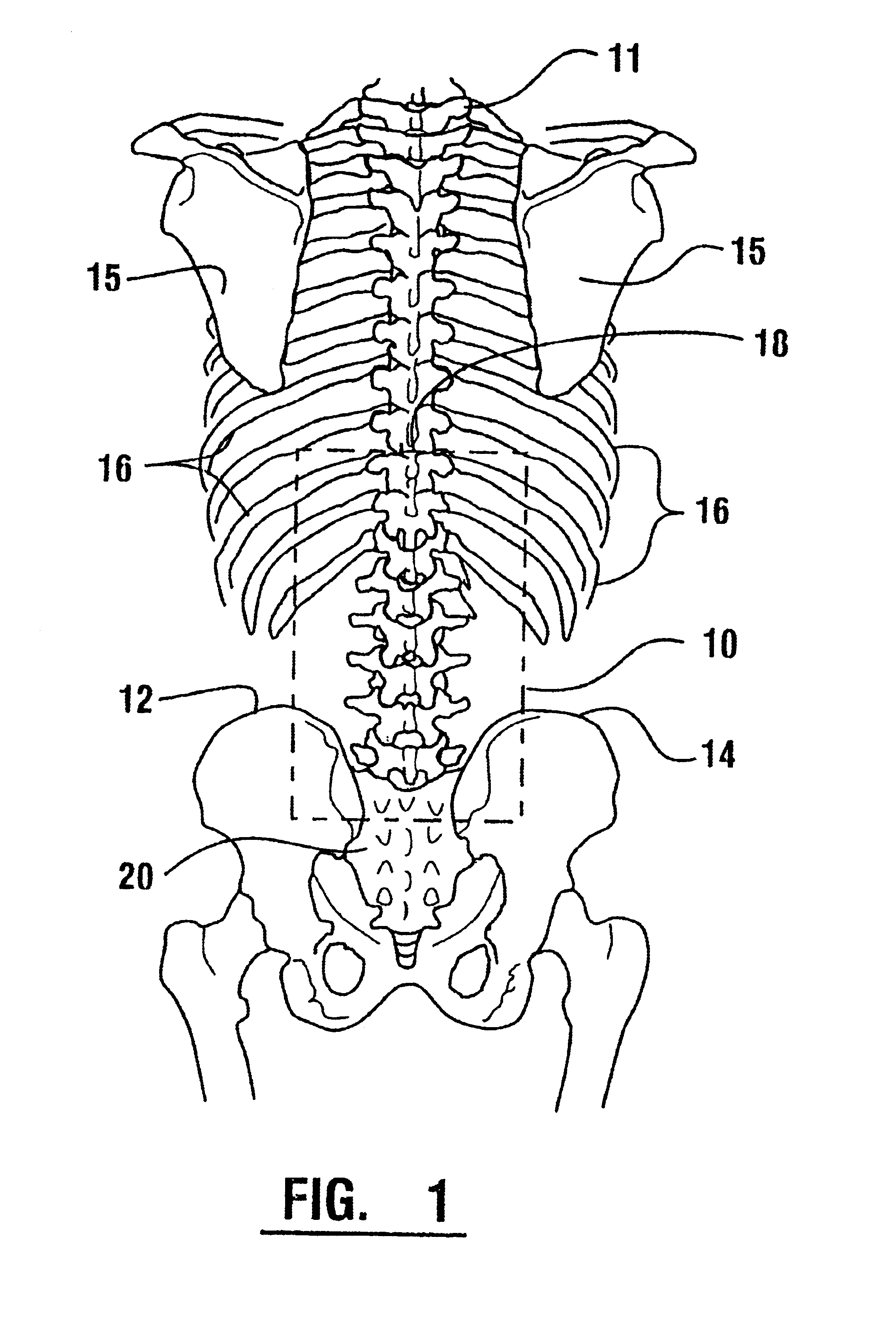
Referring now to the drawings, and initially to FIG. 1, there is shown in schematic form the sensor pad 10 of the invention positioned in relation to a partial skeletal showing of the lower back of a patient, the latter comprising a spine 11, left posterior superior iliac crest 12, right posterior superior iliac crest 14, portions of the scapula 15 and ribs 16. As will be described in greater detail hereafter, sensor pad 10 is a device for collecting electromyographic (EMG) signals from the underlying muscle stricture supporting and providing movement to the spine 11. The muscle structure is a complicated array of muscles consisting of at least sixty-nine erector and intrinsic muscles in the thoracolumbosacral spine extending from about the tenth thoracic vertebrae 18 to the sacrum 20. These are the primary muscles with which this invention is concerned and occur in layers from deep to superficial. Also formed in the superficial region of the lower back are several muscles which are...


PUM


Abstract

A system for detecting and analyzing electrical activity in the anatomy of an organism underlying an electrode array provides signals corresponding to electrical activity adjacent each electrode. Such signals are correlated to the underlying anatomy of the organism and representative outputs presented through various types of output devices. Such outputs may include variations in coloration or other qualities in correspondence with representations of underlying anatomical structures. The system includes novel electrode structures (200, 224, and 284) and methods for producing and attaching electrode arrays (240 and 280) to the organism. The exemplary form of the invention is used in connection with the diagnosis of muscle activity in the lower lumbar regions of humans. Levels of muscle activity detected are analyzed by correlation with the muscular structures underlying the electrode array. Forms of the invention may be used in other applications.

Description

TECHNICAL FIELDThis invention relates to a method and apparatus for monitoring and displaying the condition of muscles in a muscle group by the sensing and analysis of electromyographic signals derived from a non-invasive body surface electrode array positioned close to the muscle group. Particularly this invention relates to an electrode apparatus and a system for positioning and holding electrodes in a desired orientation relative to the anatomy of a patient.BACKGROUND ARTKnowledge of the presence of electromyographic (EMG) signals in the muscles of humans, and the change of these signals with muscle activity, spawned development of electronic devices and techniques for monitoring those signals for the evaluation of the muscles. Human musculature, however, involves many hundreds of muscles in various muscle groups, which interact to provide skeletal support and movement. Much of the recent development has been concerned with the techniques and / or devices for monitoring the signals...

Claims


Application Information

Patent Timeline
Patent Type & Authority Patents(United States)
IPC IPC(8): A61B5/0488A61B5/0492A61B5/04A61B5/296
CPCA61B5/04004A61B5/6831A61B5/0492A61B5/0488A61B2562/046A61B2562/0215A61B5/30A61B5/296A61B5/389
Inventor FINNERAN, MARK T.ALEXANDER, KATHRYN E.ALEXANDER, B. RUSSELLWICKHAM, JR., CHARLES E.HITCHCOCK, RICHARD L.HOWARD, SCOTT D.
Owner SPINEMATRIX
Why Eureka
Try Eureka